
Page 216 - Fundamentals of Water Treatment Unit Processes : Physical, Chemical, and Biological
P. 216
Flotation 171
8.3.3 CONTACT ZONE The diameter should be large enough such that the friction
headloss is negligible. From the manifold, the flow R is distrib-
As to mechanism, in the contact zone there are two steps.
uted through a bank of nozzles; the major change in pressure
First, the bubbles and particles must contact; the higher the between the saturator and the contact zone is across the ‘‘throat’’
concentration of bubbles, the higher the probability of contact.
of each nozzle.
Second, the bubbles that contact must attach; the fraction
In the ‘‘contact zone,’’ the bubbles released in the flow,
attaching is in the range of 0.3–0.4, depending on the portion
R, from the saturator are dispersed into the flow of floc par-
of the surface already occupied by bubbles, and other factors
ticles, Q. The ‘‘transport’’ of the bubbles occurs first by the
(Matsui et al., 1998). After attachment, the particle–bubble
random motion due to turbulence, with a fraction making
agglomerates become buoyant and rise. The ‘‘rise’’ occurs in
‘‘contact’’ with the floc. At the same time, the bubbles rise
the ‘‘separation’’ zone.
with a fraction making contact with the floc by ‘‘interception.’’
Figure 8.8 depicts the contact zone and the adjacent sep-
Once contact is made, a fraction of the particles ‘‘attach.’’ The
aration zone. Floc particles enter the contact zone where a
contact zone is where these two phases of the project occur.
fraction of the bubbles attach. The bubble–particle agglomer-
ates then rise in the separation zone and form a float layer at
the water surface, which is moved by skimmer blades to a 8.3.3.1 Floc–Bubble Transport and Attachment
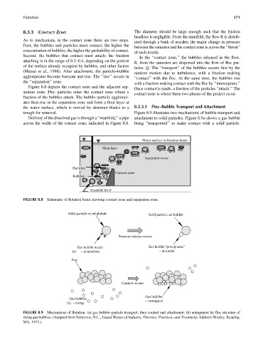
trough for removal. Figure 8.9 illustrates two mechanisms of bubble transport and
Delivery of the dissolved gas is through a ‘‘manifold,’’ apipe attachment to solid particles. Figure 8.9a shows a gas bubble
across the width of the contact zone, indicated in Figure 8.8. being ‘‘transported’’ to make contact with a solid particle.
Water surface in flotation basin
Float layer
Separation zone
Particles
Contact zone
Bubbles
Manifold for R
FIGURE 8.8 Schematic of flotation basin showing contact zone and separation zone.
Solid particle or oil globule Solid particle-air bubble
Pressure release occurs
Gas bubble nuclei Gas bubble “precipitates”
(a) —at interface —at nuclei
Floc
Contact occurs
Gas bubbles
Gas bubbles —entrapped
(b) —rising
FIGURE 8.9 Mechanisms of flotation: (a) gas bubble–particle transport, then contact and attachment; (b) entrapment by floc structure of
rising gas bubbles. (Adapted from Nemerow, N.L., Liquid Wastes of Industry, Theories, Practices, and Treatment, Addison-Wesley, Reading,
MA, 1971.)