
Page 422 - Fundamentals of Water Treatment Unit Processes : Physical, Chemical, and Biological
P. 422
Rapid Filtration 377
(a) (b)
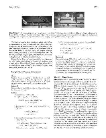
FIGURE 12.44 Contaminant injection and sampling in 51 mm (2 in.) PVC influent pipe for 76 L=min (20 gpm) pilot plant, Engineering
Research Center, Colorado State University, Fort Collins, CO. (a) Contaminant injection point upstream from static mixer. (b) Contaminant
sampling points for grab sampling and continuous flow sampling (cartridge filter sample), respectively.
The concentration of the contaminants mixed with inflow 5. N(cysts) ¼ Q(contaminant metering) C(contaminant
should be adequate to detect numbers on the effluent side (e.g., metering) t(metering time)
without the use of detection limits). For viruses and bacteria,
grab sampling is recommended for both influent and effluent at ¼ 0:01667 L= min ) 455,908 cysts=L 120 min
say 15 min intervals. For algae, cysts, and oocysts, cartridge ¼ 911,998 cysts
filters with 1 mm size may be used to collect perhaps 200 L on 1:0 million cysts
the influent sample and perhaps 1000 L of effluent sample, that
is, large enough to obtain countable numbers. Comments
Figure 12.44a shows an injection point for test organisms Cysts up to perhaps 100 million may be obtained from vari-
(or other contaminants of interest) located just upstream from ous sources. Typical numbers for injection in a large pilot
a static mixer. Figure 12.44b shows sampling points down- plant are around 10 million. As a caution, injections of
stream from the static mixer after the contaminants have been organisms in the vicinity of operating plants may be not
advisableunlessprecautionarymeasuresaretakenforproper
mixed with the raw water inflow.
isolation of the pilot plant and for disposal of solids produced
and filter effluent. The solids will be contaminated and the
Example 12.12 Metering Contaminants filter effluent should be presumed to be contaminated.
Given
Suppose the detection limit of Giardia cysts is say 0.01 12.6.1.2 Filter Column
cyst=L. Removals are about 3.5-log; assume 4-log for a The filter column is a simple tube, but a number of consid-
conservative estimate. The pilot plant flow is 76 L=min erations enter into its design. Common sizes for filter col-
(20 gpm) for a 610 mm (24 in.) square filter column. umns are 51 mm (2 in.) diameter, 102 mm (4 in.) diameter,
Required 152 mm (6 in.) diameter. For a permanent installation, a
Number of cysts in a 2000 mL volume, to be metered into 305 mm (12 in.) square size is common. To construct the
the flow over 120 min. column, clear PVC is favored because it is relatively cheap,
durable, and is easy to glue and cut without a machinist.
Solution
1. Let C(effluent) ¼ 0.01 cyst=L Piezometers taps, 6.3 mm (1=4 in.)insize, maybe spaced at
2. If log R ¼ log(C=C o ) ¼ 4.0, then, 100mmoncenters alongthe columnlengthto ascertain the
hydraulic gradient. The approximate length of the column
log (0:01=C o ) ¼ 4:0, which gives, should be the sum of length of bottom fittings to porous
C o ¼ 100 cysts=L plate þ depth of media þ increment of bed expansion during
backwash þ distance above expanded media for backwash
3. Q(contaminant metering) ¼ V(contaminant)=t(meter- effluent þ length of top fittings þ additional head desired
ing time)
such that filter runs are terminated by effluent concentration,
not by headloss limitation. The backwash flow may exit the
¼ 2000 mL=120 min
column about 300 mm (12 in.) above the expanded media, or
¼ 16:67 mL= min
whatever is necessary to avoid loss of media. The coagulated
4. Q(contaminant metering) C(contaminant metering) water flow should enter the column with low velocity such
that the medium is not disturbed. The flow is metered and
¼ Q(pp flow) C o
controlled on the influent side. The effluent flow should
(0:01667 L= min ) C(contaminant metering) leave the system by means of an overflow weir with crest
¼ (76 L= min ) (100 cysts=L) about the same elevation as the top of the media. Ball valves
C(contaminant metering) ¼ 455,908 cysts=L are the cheapest and most functional for on-off control.