
Page 417 - Fundamentals of Water Treatment Unit Processes : Physical, Chemical, and Biological
P. 417
372 Fundamentals of Water Treatment Unit Processes: Physical, Chemical, and Biological
staff, working with consultants, reporting to regulatory agen- through the appropriate pipes and channels. In modern plants,
cies, interacting with city officials, and anticipating and min- the tasks of opening and closing valves and measuring flows
imizing problems whether looking ahead to new regulations are accomplished by a SCADA system.
or responding to unexpected exigencies in ambient water
quality. This section reviews only the operation functions 12.5.2 FILTRATION HYDRAULICS
that relate to the depth filtration process.
For R 1, the hydraulics of filters follows Darcy’s law,
A sampling of the ubiquitous issues includes mud-balls,
v ¼ (k=m) i, albeit at high filtration rates (R > 1 and
air-binding of media, variable ambient water quality, unex-
pected water quality events, ripening duration, backwash dur- R 1) the ‘‘Forcheimer’’ relation, Equation E.3, i ¼ a F v þ
2
b F v , applies. For a filter in clean-bed condition, the appli-
ation, bacterial films on filter walls, and localized high
cation of Darcy’s law is straightforward and simple, that is,
backwash velocities.
headloss is linear with distance. As the filter bed clogs with
solids, however, its intrinsic permeability changes with depth
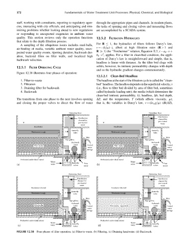
12.5.1 FILTER OPERATING CYCLE
and so the hydraulic gradient changes commensurately.
Figure 12.38 illustrates four phases of operation:
12.5.2.1 Clean-Bed Headloss
1. Filter-to-waste Theheadloss at the start ofthe filtrationcycle iscalledthe‘‘clean-
2. Filtration bed’’headloss.Theheadlossdependsonthesuperficialvelocity,v
3. Draining filter for backwash (i.e., flow to filter bed divided by area of filter bed, sometimes
4. Backwash called hydraulic loading rate); the media (which determines the
clean-bed intrinsic permeability, k); headloss, Dh; bed depth,
The transitions from one phase to the next involves opening DZ; and the temperature, T (which affects viscosity, m);
and closing the proper valves to direct the flow of water that is, the variables in Darcy’slaw, v ¼ (kr w g=m) (dh=dZ),
Operating floor Operating floor
Distribution
Distribution
channel for channel for
pre-treated
pre-treated water
water
Headwater Headwater
Butterfly Butterfly
Washwater trough A valve Washwater trough A valve
Weir Weir
Gullet Pipe gallery Gullet Pipe gallery
Backwash
Backwash
Tail-water storage Flow Tail-water storage
water water
Filter media Treated Filter media Treated
water
water
Gravel support C Gravel support C D meter
E
Perforated under-drain lateral Perforated under-drain lateral
Waste Butterfly Waste Butterfly
Flow
Flow
(a) water valves meter (b) water valves meter
Operating floor Operating floor
Distribution Distribution
channel for channel for
pre-treated pre-treated
water water
Headwater-drained Headwater-drained
Butterfly Butterfly
Washwater trough A valve Washwater trough A valve
Weir Weir
Gullet Pipe gallery Pipe gallery
Backwash
Backwash
Filter media water Treated Filter media–expanded Gullet water Treated
Flow Tail-water water Flow Tail-water water
meter storage meter storage
B
Gravel support C D Gravel support C D
E E
Perforated under-drain lateral Perforated under-drain lateral
Waste Butterfly Waste Butterfly
(c) water valves (d) water valves
FIGURE 12.38 Four phases of filter operation. (a) Filter-to-waste. (b) Filtering. (c) Draining headwater. (d) Backwash.