
Page 414 - Fundamentals of Water Treatment Unit Processes : Physical, Chemical, and Biological
P. 414
Rapid Filtration 369
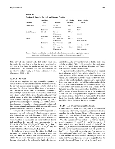
TABLE 12.11
Backwash Rates in the U.S. and Europe Practice
Sand Size Air Velocity Water Velocity
Location (mm) Sequence (m=min) (m=h)
United States 0.5–1.2 Air first 0.9–1.5
Water second 36–54
Dual media Same Same
United Kingdom 0.6–1.2 Air first 0.3–0.5
Water second 12.6–18
Dual media Water second 0.5
Europe 1–2 Air þ water first 0.9–1.5 12.6–18
Water second Same or double
Dual media Air þ water first 1.5
Water second Expand bed 0.1–0.2
2–4 Air þ water first 1.8–2.4 14.4–18
Water second Same or double
Source: Adapted from Cleasby, J.L., Backwash and underdrain considerations, unpublished paper for
short course at Colorado State University on design of filtration systems, June, 1991.
both air-wash and surface-wash. For surface-wash with alone following the air–water backwash so that the media may
backwash, the procedure is to draw the water level to about again be stratified. Table 12.11 summarizes backwash prac-
100 mm (4 in.) above the media bed and then begin the tices in the United States, the United Kingdom, and Europe
surface-wash. The sequence and time recommended are with associated air and water velocities.
as follows: surface wash, 0–4 min; backwash, 2–6 min A separate manifold=lateral pipe=orifice system is required
(Kawamura, 1999, p. 84). for the air-wash, with the laterals being placed in the support
gravel (seeMonk,1987).Thedesignofanair-washsystemis,in
principle, the same as the hydraulic design for the water back-
12.4.4.8 Air-wash
wash. In other words, the header pipes should be large so that
Air-wash is accomplished by a separate manifold system with
the pressure losses are minor and with large diameter laterals for
orifices that deliver air to the filter media. As in surface-wash,
the same reason but smaller in diameter than the header pipe
the air-wash causes particle-to-particle contacts, which is felt
because if there are n laterals, the flow is only 1=nth the flow of
necessary for effective cleaning. Three kinds of air scour are
the header pipe. The major pressure loss should be across the
(Amirtharajah and Trusler, 1982) are as follows: (1) channels of
orifices so that whatever losses there are in the headers and
air run through the bed and the air has little effect on the media
laterals there are a small proportion of the pressure loss across
not in direct contact with the channels, (2) simultaneous water
any orifice. As in the distribution of water, an objective is that
and air washes in which discrete bubbles, in moving upward,
the air flow from the furthest orifice from the header entrance
cause turbulence throughout the bed along with a high rate of
should be 5% of the flow at the header entrance.
particle contacts and improved cleaning, (3) a ‘‘subfluidization’’
transition range between the two foregoing conditions that oscil-
lates between channels and bubbles which is typical of European 12.4.4.9 Air–Water Concurrent Backwash
practice (Hewitt and Amirtharajah, 1984, p. 592). A simultaneous air–water backwash, done at subfluidization
Two types of air scouring are as follows: sequential and velocities and followed by water alone, is the most effective
concurrent and both perform well when the systems are prop- procedure for media cleaning. Figure 12.36 provides a quick
erly designed and operated (Kawamura, 1999, p. 83). As guide to velocities for both air and water and those recom-
noted in Section 12.4.4.9, however, the most effective back- mended for practice by General Filter Company (Cleasby,
wash procedure is a concurrent air–water backwash. Empir- 1991). The sequence of water and air is as follows: (1) slow
2
ical guidelines for air-wash were recommended by as water backwash at 8–15 m=h (3.5–6.1 gpm=ft ) for time 0 t
2
3
2
2
0.75–0.90 m =m =min (2.5–3.0 scf=ft =min) for ‘‘ordinary’’ 5 min with air scour at 0.014–0.10 m=h (0.5–3.5 cfm=ft ) for
2
2
3
filter beds and 0.9–1.2 m =m =min (3–4 scf=ft =min) for time 0 t 6 min; (2) stop the air scour and purge the air from
2
‘‘deep’’ filter beds (Kawamura, 1991, p. 216). the media using water backwash at 29 m=h (12 gpm=ft ) for
In the layout of an air system, the orifices should all be at time 7 t 13 min, with increase in water flow (optional) to
2
the same level so that there is the same external water pres- 45 m=h (18 gpm=ft ) for time 13 t 15 min. The procedure is
sure, and hence the same air flow from each orifice (Monk, to draw down the water level to about 100 mm (4 in.) above the
1987). An air scour will cause a dual or tri-media bed to media bed. The slow backwash should be stopped before the
become mixed and so the bed must be fluidized with water water level rises to 150 mm (6 in.) below the trough weir.