
Page 410 - Fundamentals of Water Treatment Unit Processes : Physical, Chemical, and Biological
P. 410
Rapid Filtration 365
Table CDD.2, Appendix D, which is illustrated
graphically in Figure 12.30.
4. Gravel support: The gravel support, if a generic
under-drain system is used, is graded from coarse
at bottom to fine gravel at the interface with the
media. For the top layer of gravel, garnet, with
SG 4.6, is recommended to reduce movement
potential during backwash (Monk, 1987). Recom-
mendations by Cleasby (1991) are
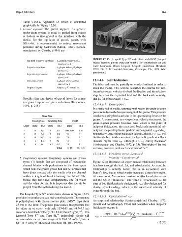
FIGURE 12.33 Leopold Type St under-drain with IMSt (Integral
Medium-to-gravel interface: d 10 (interface gravel)=d 10
Media Support) porous plate cap suitable for simultaneous air and
(medium) 4
water backwash. (From Leopold, Leopold underdrain, Brochure
Layer-to-layer fine: d 10 (layer below)=d 10 (layer
UNN-100, F. B. Leopold Company, Zelienople, PA, 1999. With
above) 2
permission.)
Layer-to-layer coarse: d 10 (layer below)=d 10 (layer
above) 4
Gravel-to-orifice: d 10 (layer above)=orifice 12.4.4.6 Bed Fluidization
size 2or 3 The filter bed must be partially or wholly fluidized in order to
Depth of layers: d(layer) 70 mm (3 in.) clean the media. This section describes the criteria for min-
imum backwash velocity for bed fluidization and the relation-
ship between the expanded bed and the backwash velocity,
Specific sizes and depths of gravel layers for a gen- that is, for v(backwash) > v mf .
eric gravel support are given as follows (Kawamura,
1991, p. 218): 12.4.4.6.1 Description
In a static bed of media, saturated with water, the grain-to-grain
pressure is due to the buoyant weight of the grains. This pressure
Sieve Size is reduced during backwash due to the upward drag forces on the
grains. At some point, as v (superficial velocity) increases, the
Passing Size Retaining Size Depth
grain-to-grain pressure becomes zero, which is the point of
Layer (mm) (in.) (mm) (in.) (mm) (in.) incipient fluidization; the associated backwash superficial vel-
1 13 1=2 19 3=4 100–150 4–6 ocity and incipient hydraulic gradient are designated, v mf and i mf ,
2 19 3=4 12 1=2 75 3 respectively. Any higher backwash velocity, that is, v > v mf ,will
3 13 1=2 6 1=4 75 3 fluidize the bed. At the same time, the hydraulic gradient will not
4 6 1=4 3 #6 75 3 increase higher than i mf ,although v > v mf during backwash
5 3 #6 1.7 #12 75 3 (Amirtharajah and Cleasby, 1972, p. 55). The height of the bed
Total 16–18 400–450 will rise, however, with each increment of ‘‘v.’’
12.4.4.6.2 Headloss versus Backwash
5. Proprietary systems: Proprietary systems are of two Velocity—Experimental
types: (1) laterals that are composed of rectangular Figure 12.34 illustrates an experimental relationship between
channel blocks with perforations in the floor upon headloss through the bed, Dh, and v(backwash). As seen, the
which rests the graded gravel bed and (2) orifices that relationship is initially linear, that is, in accordance with
have direct contact with the media with the channel Darcy’s law, but as v(backwash) increases, a transition starts.
within a length of blocks forming the lateral. The At some point, Dh remains constant as v(backwash) increases
blocks may have two compartments, one for water and the bed is ‘‘fluidized.’’ The value of v(backwash) at the
and the other for air. It is important that the air be start of bed fluidization is designated, v mf , also designated for
purged from the system during backwash. clarity, v(backwash) mf , which is the superficial velocity of
water through the bed.
The Leopold Type Se under-drain, shown in Figure 12.33,
12.4.4.6.3 Calculation of v mf
provides for simultaneous air and water backwash. The structure
is polyethylene with plastic porous plate (IMSe cap) about An empirical relationship (Amirtharajah and Cleasby, 1972;
25 mm (1 in.) thick. The porous plate causes little pressure loss Hewitt and Amirtharajah, 1984) that describes when incipient
for either air or water, with only 115–140 mm (4.5–5.5 in.) fluidization occurs is
2
water at a backwash velocity of 0.81 m=min (20 gpm=ft ). The 11 1:82 2 0:94
3:2193 10 (d 60 ) g (SG(medium) 1
Leopold Type Se and Type SLe under-drain blocks will w
v mf ¼ 0:88
3
2
accommodate an air flow range of 0.30–1.52 m =m =min at m
2
STP (1–5scfm=ft ) (Leopold, Brochure FIL-100, 1999c). (12:50)