
Page 408 - Fundamentals of Water Treatment Unit Processes : Physical, Chemical, and Biological
P. 408
Rapid Filtration 363
2. Volume Criterion for Backwash Water Assume that W (in.)
2
3
the 6 m =m criterion applies (from Amirtharajah, 0 4 8 12 16
1985, illustrated in Figure 12.31). Therefore, 1200 5000
B 51 mm (2 in.)
1000
V(backwashwater) ¼ V(loading) A(filter) 2 filters=bay W 4000
3
2
2
¼ 6:0m =m (4:27 6:10 m )=filter 2 filters=bay B = 610 mm (24 in.)
800
3
¼ 312 m =bay (82,580 gal=bay) 3000
Q (m 3 /h) 600 B = 533 mm (21 in.) Q (gpm/ft 2 )
Discussion
Backwash is usually done on a time basis. The use of a B = 457 mm (18 in.) 2000
400
backwash turbidimeter would provide a process that has a
more focused approach to backwash duration. A plot of B = 381 mm (15 in.)
backwash turbidity versus backwash water volume per 200 1000
unit area of filter bed, similar to Figure 12.31, would be B = 305 mm (12 in.)
useful for a given installation. Such a plot should be gen- 0 0
erated for each kind of raw water filtration season and 0 100 200 300 400 500
for different pretreatment conditions. To estimate the frac- W (mm)
tion of water produced used in backwash, assume HLR
2
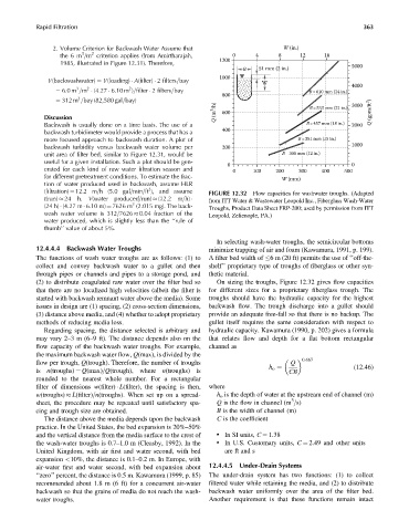
(filtration) ¼ 12.2 m=h (5.0 gal=min=ft ), and assume FIGURE 12.32 Flow capacities for washwater troughs. (Adapted
t(run) 24 h. V(water produced=run) (12.2 m=h) from ITT Water & Wastewater Leopold Inc., Fiberglass Wash-Water
3
(24 h) (4.27 m 6.10 m) ¼ 7626 m (2.015 mg). The back- Troughs, Product Data Sheet FRP-200; used by permission from ITT
wash water volume is 312=7626 0.04 fraction of the Leopold, Zelienople, PA.)
water produced, which is slightly less than the ‘‘rule of
thumb’’ value of about 5%.
In selecting wash-water troughs, the semicircular bottoms
12.4.4.4 Backwash Water Troughs minimize trapping of air and foam (Kawamura, 1991, p. 199).
The functions of wash water troughs are as follows: (1) to A filter bed width of 6 m (20 ft) permits the use of ‘‘off-the-
collect and convey backwash water to a gullet and then shelf’’ proprietary type of troughs of fiberglass or other syn-
through pipes or channels and pipes to a storage pond, and thetic material.
(2) to distribute coagulated raw water over the filter bed so On sizing the troughs, Figure 12.32 gives flow capacities
that there are no localized high velocities (albeit the filter is for different sizes for a proprietary fiberglass trough. The
started with backwash remnant water above the media). Some troughs should have the hydraulic capacity for the highest
issues in design are (1) spacing, (2) cross-section dimensions, backwash flow. The trough discharge into a gullet should
(3) distance above media, and (4) whether to adopt proprietary provide an adequate free-fall so that there is no backup. The
methods of reducing media loss. gullet itself requires the same consideration with respect to
Regarding spacing, the distance selected is arbitrary and hydraulic capacity. Kawamura (1990, p. 202) gives a formula
may vary 2–3m(6–9 ft). The distance depends also on the that relates flow and depth for a flat bottom rectangular
flow capacity of the backwash water troughs. For example, channel as
the maximum backwash water flow, Q(max), is divided by the
0:667
flow per trough, Q(trough). Therefore, the number of troughs Q
(12:46)
is n(troughs) ¼ Q(max)=Q(trough), where n(troughs) is h o ¼ CB
rounded to the nearest whole number. For a rectangular
filter of dimensions w(filter) L(filter), the spacing is then, where
w(troughs) L(filter)=n(troughs). When set up on a spread- h o is the depth of water at the upstream end of channel (m)
3
sheet, the procedure may be repeated until satisfactory spa- Q is the flow in channel (m =s)
cing and trough size are obtained. B is the width of channel (m)
The distance above the media depends upon the backwash C is the coefficient
practice. In the United States, the bed expansion is 20%–50%
and the vertical distance from the media surface to the crest of . In SI units, C ¼ 1.38
the wash-water troughs is 0.7–1.0 m (Cleasby, 1992). In the . In U.S. Customary units, C ¼ 2.49 and other units
United Kingdom, with air first and water second, with bed are ft and s
expansion <10%, the distance is 0.1–0.2 m. In Europe, with
air-water first and water second, with bed expansion about 12.4.4.5 Under-Drain Systems
‘‘zero’’ percent, the distance is 0.5 m. Kawamura (1999, p. 85) The under-drain system has two functions: (1) to collect
recommended about 1.8 m (6 ft) for a concurrent air-water filtered water while retaining the media, and (2) to distribute
backwash so that the grains of media do not reach the wash- backwash water uniformly over the area of the filter bed.
water troughs. Another requirement is that these functions remain intact