
Page 403 - Fundamentals of Water Treatment Unit Processes : Physical, Chemical, and Biological
P. 403
358 Fundamentals of Water Treatment Unit Processes: Physical, Chemical, and Biological
TABLE 12.6
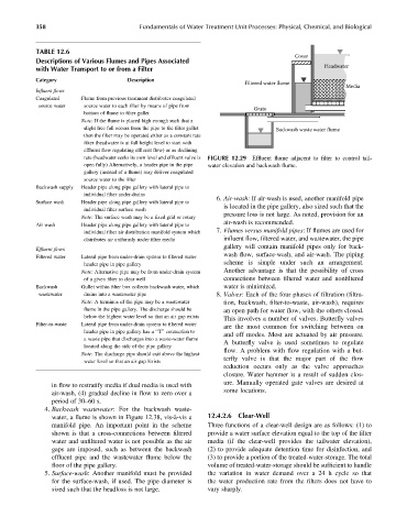
Cover
Descriptions of Various Flumes and Pipes Associated
Headwater
with Water Transport to or from a Filter
Category Description
Filtered water flume
Media
Influent flows
Coagulated Flume from previous treatment distributes coagulated
source water source water to each filter by means of pipe from
Grate
bottom of flume to filter gullet
Note: If the flume is placed high enough such that a
slight free fall occurs from the pipe to the filter gullet Backwash waste water flume
then the filter may be operated either as a constant rate
filter (headwater is at full height level to start with
effluent flow regulating effluent flow) or as declining
rate (headwater seeks its own level and effluent valve is FIGURE 12.29 Effluent flume adjacent to filter to control tail-
open fully) Alternatively, a header pipe in the pipe water elevation and backwash flume.
gallery (instead of a flume) may deliver coagulated
source water to the filter
Backwash supply Header pipe along pipe gallery with lateral pipe to
individual filter under-drains
6. Air-wash: If air-wash is used, another manifold pipe
Surface wash Header pipe along pipe gallery with lateral pipe to
is located in the pipe gallery, also sized such that the
individual filter surface wash
pressure loss is not large. As noted, provision for an
Note: The surface wash may be a fixed grid or rotary
air-wash is recommended.
Air wash Header pipe along pipe gallery with lateral pipe to
7. Flumes versus manifold pipes:If flumes are used for
individual filter air distribution manifold system which
distributes air uniformly under filter media influent flow, filtered water, and wastewater, the pipe
gallery will contain manifold pipes only for back-
Effluent flows
wash flow, surface-wash, and air-wash. The piping
Filtered water Lateral pipe from under-drain system to filtered water
scheme is simple under such an arrangement.
header pipe in pipe gallery
Note: Alternative pipe may be from under-drain system Another advantage is that the possibility of cross
of a given filter to clear well connections between filtered water and nonfiltered
Backwash Gullet within filter box collects backwash water, which water is minimized.
wastewater drains into a wastewater pipe 8. Valves: Each of the four phases of filtration (filtra-
Note: A terminus of the pipe may be a wastewater tion, backwash, filter-to-waste, air-wash), requires
flume in the pipe gallery. The discharge should be an open path for water flow, with the others closed.
below the highest water level so that an air gap exists
This involves a number of valves. Butterflyvalves
Filter-to-waste Lateral pipe from under-drain system to filtered water
are the most common for switching between on
header pipe in pipe gallery has a ‘‘T’’ connection to
and off modes. Most are actuated by air pressure.
a waste pipe that discharges into a waste-water flume
Abutterfly valve is used sometimes to regulate
located along the side of the pipe gallery
flow. A problem with flow regulation with a but-
Note: The discharge pipe should exit above the highest
terfly valve is that the major part of the flow
water level so that an air gap Exists
reduction occurs only as the valve approaches
closure. Water hammer is a result of sudden clos-
ure. Manually operated gate valves are desired at
in flow to restratify media if dual media is used with
some locations.
air-wash, (4) gradual decline in flow to zero over a
period of 30–60 s.
4. Backwash wastewater: For the backwash waste-
water, a flume is shown in Figure 12.38, vis-à-vis a 12.4.2.6 Clear-Well
manifold pipe. An important point in the scheme Three functions of a clear-well design are as follows: (1) to
shown is that a cross-connections between filtered provide a water surface elevation equal to the top of the filter
water and unfiltered water is not possible as the air media (if the clear-well provides the tailwater elevation),
gaps are imposed, such as between the backwash (2) to provide adequate detention time for disinfection, and
effluent pipe and the wastewater flume below the (3) to provide a portion of the treated-water-storage. The total
floor of the pipe gallery. volume of treated-water-storage should be sufficient to handle
5. Surface-wash: Another manifold must be provided the variation in water demand over a 24 h cycle so that
for the surface-wash, if used. The pipe diameter is the water production rate from the filters does not have to
sized such that the headloss is not large. vary sharply.