
Page 402 - Fundamentals of Water Treatment Unit Processes : Physical, Chemical, and Biological
P. 402
Rapid Filtration 357
TABLE 12.5
Filter Designs Illustrative of Practice
Q HLR Depth Headloss
d 10
3
2
Plant Plant Type (m =day) (mgday) (mm=s) (gpm=ft ) Media (mm) UC (mm) (in.) (m) (ft)
Bellingham, Washington a In-line 73 10 3 19.3 2.72 4.0 Anthracite 1.10 467 18 4.86 16
Sand 0.53 305 12
Garnet 0.35 76 3
838 33
b 3
Oakland In-line 662 10 175 3.40 5.0 Anthracite 0.9 1.5 457 18 1.83 6
Orinda Plant Sand 0.5 1.6 305 12
Garnet 0 0
762 30
Los Angeles b Direct 2270 10 3 600 9.03 13.3 Anthracite 1.5 1.5 1829 72 2.43 8
Aqueduct Plant Sand 0
Garnet 0
1829 72
Tuscaloosa b Conventional 57 10 3 15 2.72 4.0 Anthracite 1 1.7 419 16.5 1.83 6
Ed E. Love Plant Sand 0.55 1.8 229 9
Garnet 0.28 2.2 114 4.5
762 30
Corvallis b Conventional 80 10 3 21 5.09 7.5 Anthracite 1.1 1.3 533 21 2.43 8
H. D. Taylor Plant Sand 0.4 1.3 305 12
Garnet 0
838 33
Las Vegas b Conventional 1550 10 3 400 3.40 5.0 Anthracite 1.1 1.7 483 19 2.43 8
A. M. Smith Plant Sand 0.5 1.8 229 9
Garnet 0.28 2.2 38 1.5
750 30
a
Hendricks et al. (2000, p. 198); total media depth 838 mm (33 ft); depth of each layer was estimated based on photograph of display section.
b
Cleasby et al. (1989), Appendix B of report.
2. Filtered water: The drawing of Figure 12.29 shows a
cross section of a flume for filtered water; the flume
is along the length of a bank of filters with effluent
weir at one end controlling depth. For such a method
of collecting filtered water, the flume should be
covered and should have provision for chlorine add-
ition to control microbial films. Usually, the filtered
water is collected by means of a common header
pipe located in the pipe gallery. The open channel
is an alternative depiction, indicating that a head
difference must be provided between the headwater
and the tailwater.
3. Backwash header pipe: A backwash header pipe,
sized to serve one filter at a time, runs the length of
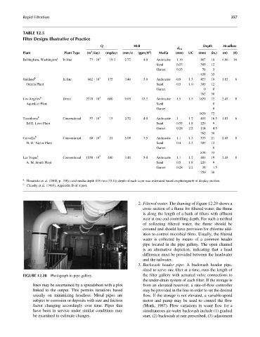
FIGURE 12.28 Photograph in pipe gallery. the filter gallery with actuated valve connections to
the under-drain system of each filter. If the storage is
lines may be ascertained by a spreadsheet with a plot from an elevated reservoir, a rate-of-flow controller
linked to the output. This permits iterations based may be provided in the line in order to set the desired
usually on minimizing headloss. Metal pipes are flow. If the storage is not elevated, a variable-speed
subject to corrosion or deposits with size and friction motor and pump may be used to control the flow
factor changing accordingly over time. Pipes that (Monk, 1987). Flow variations in water flow for a
have been in service under similar conditions may simultaneous air-water backwash include (1) gradual
be examined to estimate changes. start, (2) backwash at rate prescribed, (3) adjustment