
Page 401 - Fundamentals of Water Treatment Unit Processes : Physical, Chemical, and Biological
P. 401
356 Fundamentals of Water Treatment Unit Processes: Physical, Chemical, and Biological
Table 12.5 shows some media designs that illustrate the range
of practice for drinking water treatment. Plant capacities and
filtration rates are given also. Concerning the UC, a value of
about 1.5 is used frequently in practice, with the ideal being 1.0;
lower values provide higher void volume for floc storage and
longer filter runs (Kawamura, 1999, p. 81). The coarse media
deep bed filter has found increasing favor because of longer
filter runs and has been used with higher filtration velocities.
12.4.2.5 Pipe Gallery
Figure 12.28 shows a pipe gallery with header pipes on each
side serving adjacent filters. The pipes are color coded and
labeled. Table 12.6 lists the categories of influent and effluent
flumes and pipes that serve a bank of filters.
1. Manifold pipes: Those pipes that deliver or receive
water to or from several pipe ‘‘laterals’’ are, by
definition, ‘‘manifold’’ pipes (‘‘header’’ pipe). The
water flow exiting each lateral pipe or orifice must
be approximately the same (achieved by using a
large header pipe so that the pressure loss is small).
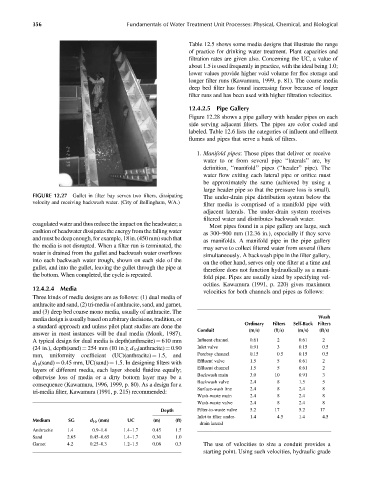
FIGURE 12.27 Gullet in filter bay serves two filters, dissipating The under-drain pipe distribution system below the
velocity and receiving backwash water. (City of Bellingham, WA.)
filter media is comprised of a manifold pipe with
adjacent laterals. The under-drain system receives
filtered water and distributes backwash water.
coagulated water and thus reduce the impact on the headwater; a
Most pipes found in a pipe gallery are large, such
cushion of headwater dissipates the energyfromthe falling water
as 300–900 mm (12.36 in.), especially if they serve
and mustbedeepenough, for example,18in.(450mm) suchthat
as manifolds. A manifold pipe in the pipe gallery
the media is not disrupted. When a filter run is terminated, the
may serve to collect filtered water from several filters
water is drained from the gullet and backwash water overflows simultaneously. A backwash pipe in the filter gallery,
into each backwash water trough, shown on each side of the on the other hand, serves only one filter at a time and
gullet, and into the gullet, leaving the gullet through the pipe at therefore does not function hydraulically as a mani-
the bottom. When completed, the cycle is repeated. fold pipe. Pipes are usually sized by specifying vel-
ocities. Kawamura (1991, p. 220) gives maximum
12.4.2.4 Media
velocities for both channels and pipes as follows:
Three kinds of media designs are as follows: (1) dual media of
anthracite and sand, (2) tri-media of anthracite, sand, and garnet,
and (3) deep bed coarse mono media, usually of anthracite. The
Wash
media design is usually based on arbitrary decisions, tradition, or
Ordinary Filters Self-Back Filters
a standard approach and unless pilot plant studies are done the
Conduit (m=s) (ft=s) (m=s) (ft=s)
answer in most instances will be dual media (Monk, 1987).
A typical design for dual media is depth(anthracite) ¼ 610 mm Influent channel 0.61 2 0.61 2
(24 in.), depth(sand) ¼ 254 mm (10 in.); d 10 (anthracite) ¼ 0.90 Inlet valve 0.91 3 0.15 0.5
mm, uniformity coefficient (UC)(anthracite) ¼ 1.5, and Forebay channel 0.15 0.5 0.15 0.5
d 10 (sand) ¼ 0.45 mm, UC(sand)¼ 1.5. In designing filters with Effluent valve 1.5 5 0.61 2
layers of different media, each layer should fluidize equally; Effluent channel 1.5 5 0.61 2
Backwash main 3.0 10 0.91 3
otherwise loss of media or a dirty bottom layer may be a
Backwash valve 2.4 8 1.5 5
consequence (Kawamura, 1996, 1999, p. 80). As a design for a
Surface-wash line 2.4 8 2.4 8
tri-media filter, Kawamura (1991, p. 215) recommended:
Wash-waste main 2.4 8 2.4 8
Wash-waste valve 2.4 8 2.4 8
Depth Filter-to-waste valve 5.2 17 5.2 17
Inlet to filter under- 1.4 4.5 1.4 4.5
Medium SG d 10 (mm) UC (m) (ft)
drain lateral
Anthracite 1.4 0.9–1.4 1.4–1.7 0.45 1.5
Sand 2.65 0.45–0.65 1.4–1.7 0.30 1.0
Garnet 4.2 0.25–0.3 1.2–1.5 0.08 0.3 The use of velocities to size a conduit provides a
starting point. Using such velocities, hydraulic grade