
Page 399 - Fundamentals of Water Treatment Unit Processes : Physical, Chemical, and Biological
P. 399
354 Fundamentals of Water Treatment Unit Processes: Physical, Chemical, and Biological
Legend
X Valve on/off
Backwash X Valve-reg.
water
storage P Pump
Headwater Flow meter
Influent
Washwater trough X Water surface
Surface wash X P
Gullet
Waste Treated
Filter media X X P water
P Air
Air wash X storage
Gravel support X
X
Under-drain lateral Filtered water
Air lateral
X
Filter-to-waste
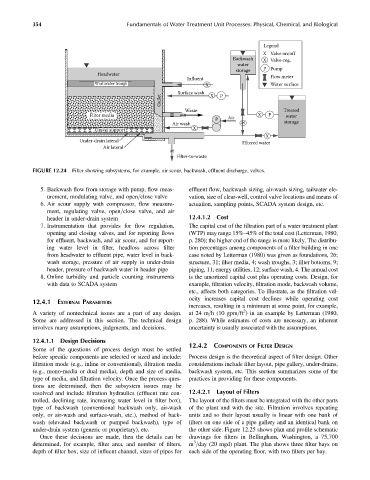
FIGURE 12.24 Filter showing subsystems, for example, air scour, backwash, effluent discharge, valves.
5. Backwash flow from storage with pump, flow meas- effluent flow, backwash sizing, air-wash sizing, tailwater ele-
urement, modulating valve, and open=close valve vation, size of clear-well, control valve locations and means of
6. Air scour supply with compressor, flow measure- actuation, sampling points, SCADA system design, etc.
ment, regulating valve, open=close valve, and air
header in under-drain system 12.4.1.2 Cost
7. Instrumentation that provides for flow regulation, The capital cost of the filtration part of a water treatment plant
opening and closing valves, and for reporting flows (WTP) may range 15%–45% of the total cost (Letterman, 1980,
for effluent, backwash, and air scour, and for report- p. 280); the higher end of the range is more likely. The distribu-
ing water level in filter, headloss across filter tion percentages among components of a filter building in one
from headwater to effluent pipe, water level in back- case noted by Letterman (1980) was given as foundations, 26;
wash storage, pressure of air supply in under-drain structure, 31; filter media, 4; wash troughs, 3; filter bottoms, 9;
header, pressure of backwash water in header pipe piping, 11; energy utilities, 12; surface wash, 4. The annual cost
8. Online turbidity and particle counting instruments is the amortized capital cost plus operating costs. Design, for
with data to SCADA system example, filtration velocity, filtration mode, backwash volume,
etc., affects both categories. To illustrate, as the filtration vel-
ocity increases capital cost declines while operating cost
12.4.1 EXTERNAL PARAMETERS
increases, resulting in a minimum at some point, for example,
2
A variety of nontechnical issues are a part of any design. at 24 m=h (10 gpm=ft ) in an example by Letterman (1980,
Some are addressed in this section. The technical design p. 288). While estimates of costs are necessary, an inherent
involves many assumptions, judgments, and decisions. uncertainty is usually associated with the assumptions.
12.4.1.1 Design Decisions
12.4.2 COMPONENTS OF FILTER DESIGN
Some of the questions of process design must be settled
before specific components are selected or sized and include: Process design is the theoretical aspect of filter design. Other
filtration mode (e.g., inline or conventional), filtration media considerations include filter layout, pipe gallery, under-drains,
(e.g., mono-media or dual media), depth and size of media, backwash system, etc. This section summarizes some of the
type of media, and filtration velocity. Once the process ques- practices in providing for these components.
tions are determined, then the subsystem issues may be
resolved and include filtration hydraulics (effluent rate con- 12.4.2.1 Layout of Filters
trolled, declining rate, increasing water level in filter box), The layout of the filters must be integrated with the other parts
type of backwash (conventional backwash only, air-wash of the plant and with the site. Filtration involves repeating
only, or air-wash and surface-wash, etc.), method of back- units and so their layout usually is linear with one bank of
wash (elevated backwash or pumped backwash), type of filters on one side of a pipe gallery and an identical bank on
under-drain system (generic or proprietary), etc. the other side. Figure 12.25 shows plan and profile schematic
Once these decisions are made, then the details can be drawings for filters in Bellingham, Washington, a 75,700
3
determined, for example, filter area, and number of filters, m =day (20 mgd) plant. The plan shows three filter bays on
depth of filter box, size of influent channel, sizes of pipes for each side of the operating floor, with two filters per bay.