
Page 398 - Fundamentals of Water Treatment Unit Processes : Physical, Chemical, and Biological
P. 398
Rapid Filtration 353
C/C
0 o 1.0
Z =0 0
C(Z) t =0 Saturated zone (t1):
Z (sat)t1 ∂C Z<Z(sat) =0 ∂σ Z<Z(sat) =0
∂t
∂t
–λt
Iwasaki relation: C/C =e
o
Capacity-limited and shear limited zone:
C(Z) t =t1
∂C =–ν ∂C + 1 ε ∂σ
Filter column Z Inflection point: C/C o (ip) ∂t o r
∂Z
∂t
∂σ
= k 1 νC(F –σ) =–k νε σ
2
∂t K o (1–√σ/F) 3
Convection-limited zone:
C/C = C/C o (ip) e –λt
o
Z= Z o Z o
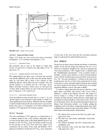
FIGURE 12.23 Zones of wave front.
12.3.4.3 Zones of Wave Front of each zone of the wave front and the associated equations
Figure 12.23 shows the zones of the wave front as described helps to understand the depth filtration process.
by Equation 12.29 combined with Equation 12.35.
12.4 DESIGN
12.3.4.3.1 Saturated Zone
Design has two parts: process design and design of subsystem
The saturated zone is seen as the region in which both
support. In the process design the objectives are two: (1) to
qC=qZ ¼ 0 and qs=qZ ¼ 0 and by the same token, qC=qt ¼ 0
ensure an economical ‘‘length-of-run’’ and (2) to maximize the
and qs=qt ¼ 0.
‘‘net-water-production.’’ The ‘‘length-of-run’’ is defined when
the ‘‘breakthrough concentration,’’ such as particle counts or
12.3.4.3.2 Uptake-Limited and Shear Zone
turbidity, exceeds some criterion, or when terminal headloss
The uptake-limited and shear zone is between the saturated occurs. Ideally, breakthrough occurs just before terminal head-
zone and the inflection point. In this zone, the specific deposit loss. The ‘‘net-water-production’’ is defined as the total water
takes up void space and so there is less capacity to take production per unit area of filter minus requirements for back-
additional deposit, which affects the rate of uptake. Also, the wash, filter-to-waste, and other support functions and is related
specific deposit, as it intrudes into the void space, causes
not only to length-of-run, but also to other factors, for example,
higher interstitial velocities, which causes an increased rate
superficial filtration velocity (the same as HLR).
of shear. Both of these effects are seen in the first and second
To achieve a design that meets the process objectives, a pilot
parts of Equation 12.46, respectively.
plant study is advisable. One reason is that ‘‘every water is
different,’’ a cliché in the industry, but true. The output of a
12.3.4.3.3 Advection-Limited Zone
process design is a sizing of the process components, for
From the inflection point forward, that is, at all Z Z ip , the example, the filter bed area, media selection, media depth, and
specific deposit is not sufficient to limit uptake of solids or to an estimate of terminal headloss. These factors, then ‘‘drive’’ the
cause significant increase in shear. Therefore, the rate of uptake rest of the design, that is, the subsystems that support the process
of solids is limited only by the rate of advection to a given slice. design. Such subsystems include, very broadly, getting the
In this zone, since s 0, Equation 12.29 when combined with coagulated water to the filters, transporting treated water, back-
Equation 12.35 approaches the Iwasaki equation. washing filters, and processing wastewaters. Figure 12.24 illus-
trates major subsystem groups, which include
12.3.5 SUMMARY
1. The influent flow system to the filter box gullet with
The Adin and Rebhun (1977) approach, as outlined above, is open=close valve
a coherent model in that it has rational components and it 2. The filter box with media, under-drain, wash-water
accounts for the three zones of the depth filtration process. By trough, gullet
inclusion of the [qC=qC] obs term, the model can also account 3. The effluent discharge with flow measurement and
for the advance of the wave front with time. Figure 12.23 modulating valve
summarizes the key ideas of the Adin and Rebhun (1977) 4. The backwash water waste line from filter gullet,
approach modified to include the [qC=qC] obs term. Inspection with open=close valve