
Page 400 - Fundamentals of Water Treatment Unit Processes : Physical, Chemical, and Biological
P. 400
Rapid Filtration 355
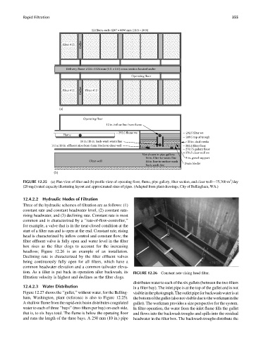
12 filters, each: 4267 × 6096 mm (14 ft×20 ft)
Gullet
Filter #12
Delivery flume 1524× 1524 mm (5 ft × 5 ft) cross-section located under
Operating floor
Gullet
Filter #12 Filter #12
(a)
Operating floor
12 in. inflow line from flume
292.5 flume ws 292.5 filter ws
Flume
289.5 top of trough
16 in./18 in. back-wash waste line 33 in. dual media
14 in./18 in. effluent pipe from drain blocks to clear well 282.5 filter floor
278.75 gallery floor
276.5 clear-well ws
Not shown in pipe gallery:
16 in. filter-to-waste line 9 in. gravel support
Clear-well 14 in. line to surface wash
Back-wash line Drain blocks
(b)
3
FIGURE 12.25 (a) Plan view of filter and (b) profile view of operating floor, flume, pipe gallery, filter section, and clear well—75,700 m =day
(20 mgd) rated capacity illustrating layout and approximated sizes of pipes. (Adapted from plant drawings, City of Bellingham, WA.)
12.4.2.2 Hydraulic Modes of Filtration
Three of the hydraulic schemes of filtration are as follows: (1)
constant rate and constant headwater level, (2) constant rate-
rising headwater, and (3) declining rate. Constant rate is most
common and is characterized by a ‘‘rate-of-flow-controller,’’
for example, a valve that is in the near-closed condition at the
start of a filter run and is open at the end. Constant rate, rising
head is characterized by inflow control and constant flow; the
filter effluent valve is fully open and water level in the filter
box rises as the filter clogs to account for the increasing
headloss; Figure 12.26 is an example of an installation.
Declining rate is characterized by the filter effluent valves
being continuously fully open for all filters, which have a
common headwater elevation and a common tailwater eleva-
tion. As a filter is put back in operation after backwash, its FIGURE 12.26 Constant rate–rising head filter.
filtration velocity is highest and declines as the filter clogs.
distributes water to each of the six gullets(between the two filters
12.4.2.3 Water Distribution in a filter bay). The inlet pipe is at the top of the gullet and is not
Figure 12.27 shows the ‘‘gullet,’’ without water, for the Belling- visibleinthephotograph.Theoutletpipeforbackwashwaterisat
ham, Washington, plant (reference is also to Figure 12.25). thebottomofthegullet(alsonotvisibleduetotheworkmaninthe
Ashallow flume from the rapid-mix basin distributes coagulated gullet). The workman provides a size perspective for the system.
water to each of three ‘‘bays’’ (two filters per bay) on each side, In filter operation, the water from the inlet flume fills the gullet
that is, to six bays total. The flume is below the operating floor and flows into the backwash troughs and spills into the residual
and runs the length of the three bays. A 250 mm (10 in.) pipe headwater in the filter box. The backwash troughs distribute the