
Page 395 - Fundamentals of Water Treatment Unit Processes : Physical, Chemical, and Biological
P. 395
350 Fundamentals of Water Treatment Unit Processes: Physical, Chemical, and Biological
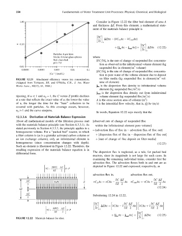
1.00 Consider in Figure 12.22 the filter bed element of area A
and thickness DZ. From this element, a mathematical state-
ment of the materials balance principle is
qC
DZAe ¼ [ vC in Ae vC out Ae]
qt
o
α 0.10
qC
DZAe
þ [j Ae j Ae] þ (12:22)
qt
in out
r
Particles: 4 μm latex
Media: 0.4 mm glass spheres where
Bed: clean-bed [qC=qt] o is the rate of change of suspended floc concentra-
pH= 7.0
tion as observed in the infinitesimal volume element (kg
0.01 3
suspended floc in element=m volume)
0.00001 0.0001 0.001 0.01 0.1
[qC=qt] r is the rate of change of suspended floc concentra-
++
[Ca ] (mol/L)
tion in pore water of the volume element due to deposit
3
FIGURE 12.21 Attachment efficiency versus ion concentration. on filter media (kg suspended floc in element=m vol-
(Adapted from Tobiason, J.E. and O’Melia, C.R., J. Am. Water ume of element)
Works Assoc., 80(12), 61, 1988.) j in is the dispersion flux density to infinitesimal volume
2
element (kg suspended floc=m =s)
j out is the dispersion flux density out from infinitesimal
2
ripening, if a 1 and a p ¼ 1, the C versus Z profile declines volume element (kg suspended floc=m =s)
2
at a rate that reflects the exact value of a; the lower the value A is the cross section area of column (m )
of a, the longer the time for the ‘‘bare’’ collectors to be v is the interstitial flow velocity, that is, Q=Ae (m=s)
covered with particles. As this coverage occurs, however,
a p 1 and the curve steepens.
In words, Equation 12.22 says merely that the
12.3.3.6 Derivation of Materials Balance Expression
About all mathematical models of the filtration process start [observed rate of change of suspended floc
with the materials balance principle (see Section 4.3.3.1). As within the infinitesimal element pore volume]
stated previously in Section 4.3.3.3, the principle applies to a
¼ [advection flux of floc in advection flux of floc out]
homogeneous volume. For a ‘‘packed bed’’ reactor, in which
a filter column is (as is a granular activated carbon column or þ [dispersion flux of floc in dispersion flux of floc out]
an ion exchange column), only an infinitesimal element is þ [rate of change of floc deposit on filter media]
homogeneous (since concentration changes with depth). (12:23)
Such an element is illustrated in Figure 12.22. Therefore, the
resulting expression of the materials balance equation is in
The dispersion flux is neglected, as a rule, for packed bed
differential form.
reactors, since its magnitude is not large for such cases. In
examining the remaining individual terms, consider first the
advection flux. The advection fluxes both in and out are as
∂(vC) ΔZ depicted in Figure 12.22 and expressed, respectively, as
vC– • A P
•
∂Z 2
advection flux in, advection flux out,
qC DZ qC DZ
ΔZ
vAPC Z vC in Ae ¼ vCAe Ae vC out Ae ¼ vCAe þ Ae
2 qZ 2 qZ 2
(12:24)
ΔZ
ΔZ
Substituting 12.24 in 12.22,
2
qC qC DZ qC DZ
DZAe ¼ vCAe v Ae vCAe þ v Ae
∂(vC) ΔZ qt o qZ 2 qZ 2
•
vC+ • A P
∂Z 2
qC
DZAe (12:25)
þ [j Ae j Ae] þ
in out qt
FIGURE 12.22 Materials balance for slice. r