
Page 55 - Fundamentals of Water Treatment Unit Processes : Physical, Chemical, and Biological
P. 55
10 Fundamentals of Water Treatment Unit Processes: Physical, Chemical, and Biological
The traveling bridge backwashes each cell individually
and moves continuously from one end of the filter bed to
the other and back again. The flow through each cell declines
as the media clogs and is restored to the clean-bed level
after backwash.
1.4.1.1.3 Colorado Springs
Because of a drought during the period 1955–1959, the City
of Colorado Springs (Colorado Springs, c. 1972) has had
tertiary treatment following traditional treatment since 1960.
This initial treatment was filtration only and the water was
used for golf course and park irrigation, and was later called
the ‘‘irrigation circuit’’; the treatment capacity was Q ¼ 0.394
3
m =s (9.0 mgd). In 1970, a second treatment train was added
and was called an ‘‘industrial circuit,’’ with capacity 0.0876
3
m =s (2.0 mgd). The effluent was used for cooling tower water
at a municipal power plant with the cost of treatment about
3
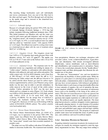
$0.07=m or $260=mg. FIGURE 1.4 GAC columns for tertiary treatment at Colorado
Springs, c. 1972.
1.4.1.1.3.1 Irrigation Circuit The irrigation circuit had
four 3.658 m (12 ft) diameter dual media pressure filters with
2
filtration velocity 36.7 m=h (15 gpm=ft ). The media was lime precipitation, filtration, ion exchange, adsorption with
0.91 m (3 ft) of 1.5 mm sand on the bottom with 1.52 m (5 ft) activated carbon, ozone oxidation=disinfection, hyper-filtra-
of 2.8 mm anthracite on top. tion, and chlorination. Side streams investigated different
disinfectants, various membranes such as micro-filtration
1.4.1.1.3.2 Industrial Circuit The treatment train for the and ultrafiltration, and ozonation prior to adsorption. Figure
industrial circuit was coagulation and settling by means of a 1.5 shows the overall plant schematic (for the ‘‘health-effects’’
‘‘solids-contact’’ clarifier, re-carbonation with carbon dioxide, treatment train) and three photographs that illustrate the sub-
filtration with anthracite and sand, and carbon adsorption. The stantial size of the plant.
solids-contact unit, 14.63 m (48 ft) diameter, used a lime dose The plant was ‘‘demonstration’’ size, and was intended to
of 300–350 mg=L of CaO, which raised the pH to 11.5. demonstrate the feasibility of direct potable reuse. While the
Following the solids contact unit, the pH was lowered to 7.0 purpose of a pilot plant is to develop design guidelines for a
by carbon dioxide (from furnace gas used for carbon regen- full-scale plant, a demonstration plant is much larger in size
eration) supplemented by sulfuric acid. Filtration using coarse and may have several purposes, both technical and political.
media was the next step in order to provide redundancy in The former relate to such issues as long-term health effects due
solids removal in the event of upset of the solids-contact to trace amounts of organics, the cost of operation, the man-
clarifier. Carbon adsorption by GAC was the next step, power required, reliability, and the assessment of unforeseen
which used two columns in series (Figure 1.4). Each column issues (such as the durability of the lining of the carbon col-
was 6.096 m (20 ft) diameter and 4.267 m (14 ft) high, packed umns). This does not mean that process issues are ignored, but
with 3.048 m (10 ft) of 8 30 mesh GAC with mass only that the emphasis shifts (as opposed to a pilot plant) to
3
41,864 kg (94,000 lb). For the design flow of 0.0876 m =s questions that require experience at a full-scale level of oper-
(2.0 mgd), the hydraulic loading rate was 10.39 m=h ation. The political aspects are equally important. The reuse
2
(4.25 gpm=ft ). Removal of COD was 0.50–0.60 kg COD=kg plant had an attractive, architect-designed, exterior appearance
carbon (0.50–0.60 lb COD=lb carbon). The carbon columns with equally pleasing interior. A water fountain of its product
were backwashed daily. water was located in the lobby, and the plant hosted innumer-
able tours and published many papers and had high visibility
1.4.1.1.4 Denver Reuse Demonstration Plant from local to international levels. The program to implement
3
The Denver Reuse Demonstration Plant, Q ¼ 0.044 m =s potable water reuse had included the issues of public accept-
(1.0 mgd), was in operation in the period 1985–1991. The ance, and confidence and need for political support.
source water was effluent from the nearby Denver Metro
WWTP (called Denver Metro Water Reclamation Plant).
1.4.2 INDUSTRIAL WASTEWATER TREATMENT
The ‘‘reuse plant’’ treated water that exceeded standards for
potable water. Regarding industrial wastewater treatment, the treatment tech-
The plant cost was $20 million with about $10 million for nologies are usually the minimum required to meet the regu-
studies to determine health risks. The treatment train included latory requirements in force. This may range from settling to