
Page 92 - Fundamentals of Water Treatment Unit Processes : Physical, Chemical, and Biological
P. 92
Models 47
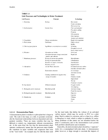
TABLE 3.1
Unit Processes and Technologies in Water Treatment
Unit Process Principle Technology
1. Screening Sieving Bar screens
Coarse screening
Microscreening
2. Sedimentation Gravity force Plain sedimentation
Flocculant settling
Flotation
Oil separation
Grit chambers
Aerated grit chambers
3. Coagulation Charge neutralization Rapid mix=coagulants
4. Flocculation Turbulence Paddle wheels
Baffles
5. Chemical precipitation Equilibrium concentration is exceeded Softening
Phosphate removal
Heavy metal removal
6. Filtration Adsorption on biofilm Slow sand
Adsorption between charge-neutralized Rapid rate
particle and collector
7. Membrane processes Sieving of micron-size particles Microfiltration
Sieving of macromolecules Ultrafiltration
Retention of organic molecules Nanofiltration
Retention of ions Hyperfiltration
8. Adsorption van der Waals attraction Powdered activated carbon
Granular activated carbon
Electrostatic attraction Ion exchange
Activated alumna
9. Oxidation Creating conditions for negative free Ozone
energy of reaction Chlorine dioxide
Supercritical
Wet air
Chemical oxidation
10. Gas transfer Diffusion transport Oxygen transfer
Air stripping
11. Biological aerobic treatment Microbial growth Activated sludge
Fixed film reactors
12. Biological anaerobic treatment Microbial growth Digestors
Lagoons
13. Disinfection Oxidation Chlorine
Ozone
UV
3.2.3.3 Demonstration Plants for the steel tanks that define the volume of an activated
A demonstration plant is similar to a pilot plant but is larger in carbon reactor, which may be acrylic or PVC in a pilot
scale. The scale is too large, as a rule, to generate economic- plant. Steel is subject to corrosion, and so a liner (e.g., rubber
ally the functional relationships between dependent and inde- or fiberglass) is used, which is subject to pinholes or cracks.
pendent variables. There are many variables that may be Many problems of this nature are not identified before the
difficult to control, e.g., temperature, influent concentration, plant is constructed, and so the demonstration scale permits
etc. At the same time, the fact that the demonstration plant both problem identification and evaluation.
operates continuously means that the processes must handle Ostensibly, the demonstration plant should be a ‘‘capstone’’
the variations in input variables and exigencies that exist study for a contemplated full-scale plant. A demonstration
in the ‘‘real world.’’ An example may be with the liner used plant, however, is large enough to ascertain the impacts of