
Page 122 - Gas Purification 5E
P. 122
1 12 Gas Pur$cation
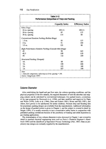
Table 2-12
Performance Comparison of Trays and Packing
Capacity Index Efficiency Index
Valve Trays
%-in. spacing 100 (1) 100 (1)
18-in. spacing 83 133
30-in. spacing 114 80
Conventional Random Packing (Ballast Rings)
1.5-in. 83 123
2-in. 91 100
3.5-in. 121 88
High-Performance Random Packing (Cascade Mini Rings)
#2 98 143
a.5 109 120
#3 132 100
Structured Packing (Gempak)
4A 88 385
3A 109 268
2A 125 188
1A 167 109
Note:
I. Basis for comparison. valve trays at 24-in. spacing = 100.
Source: Gangriwala (1987)
Column Diameter
After establishing the liquid and gas flow rates, the column operating conditions, and the
physical properties of the two streams, the required diameters of both the absorber and strip-
ping column can be calculated by conventional techniques. For packed towers, correlations
of the type proposed by Sherwood et al. (1938), and later modified and improved by Elgin
and Weise (1939): Lobo et al. (1944), Zenz and Eckert (1961), Kister and Gill (1991), and
others, have proven to be satisfactory for amine solutions. Pressure drop and flooding data
for proprietary packing designs are available from the manufacturers. Additional information
on the design of packed towers is given in Chapter 1, and the subject is covered in detail by
Smgle (1994). It is usually necessary to use a conservative safety factor in conjunction with
published packing correlations because of the possibility of foaming and solids deposition in
gas treating applications.
The determination of tray column diameters is also discussed in Chapter 1 and covered in
detail in standard chemical engineering texts such as Perry’s Chemical Engineer’s Hand-
book (1963) and the Handbook ofseparation Process Technology (Fair, 1987). Data on pro-
prietary tray designs are normally supplied by the manufacturers.