
Page 127 - Gas Purification 5E
P. 127
Alkanolamines for Hydrogen Surfide and Carbon Dioxide Removal 11 7
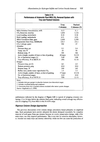
Table 2-1 5
Performance of Ammonia Plant MEA C02 Removal System with
Tray and Packed Columns
Tray Packed
Columns Columns (3)
MEA Solution Concentration, wt% 31.5 31.1
C02 Removal, tondday 1,018 1,124
Lean Loading, moledmole 0.18 0.18
Rich Loadin,., moledmole 0.5 1 0.53
MEA Circulation Rate, gpm 2,450 2,350
Regenerator Heat Duty, MMBtu/hr 123.7 131.1
C02 Leakage, ppmv 502 27
Absorber
Pressure drop, psi 9.3 5.4
Temp. rise."F 53 50
Bottom temp.,'F 204 166
Active height, number of trays or feet of packing 20 trays 31.5 ft
No. of theoretical stages (1) 3.60 3.88
Tray efficiency, 8 or HETP, ft 18% 8.1 ft
Stripper
Pressure drop, psi (2) 4.5 2.5
Bottom pressure, psig 12.0 10.0
Bottom temp.,'F 249 245
Reflux ratio, moles water vapor/mole C02 1.5 1.2
Active height, number of trays, or feet of packing 17 trays 31.5 ft
No. of theoretical stages 12.8 15.0
Tray efficiency, % or HETF', ft 70% 2.1 ft
Notes:
1. Includes inlet gas sparger in absorber bottoms (one theoretical stagej.
2. Includes overhead piping and condenser.
3. Conversion from tray to packed columns included other minor system changes.
Source: Gagliardi et al. (1989)
performance indicated by the diagram of Figure 2-81 is typical of stripping columns con-
taining 12 to 16 trays below the solution feed point, indicating overall average tray efficien-
cies for stripping C02 from MEA in the 5047% range.
Rigorous Column Design Approaches
The previous discussions cover column design procedures based primarily on empirical
data. Such procedures have proven adequate for plants designed essentially for complete
removal of acid gases from gas streams because an overly conservative design, with a few
extra trays, can only improve performance. This is not true for selective absorption, howev-
er, because too many trays can destroy selectivity; while too few can cause the poduction of