
Page 147 - gas transport in porous media
P. 147
Sahimi et al.
140
even stronger when the mobility ratio M > 1. Another phenomenon that affects mis-
cible displacements in stratified media is the crossflow of displacing and displaced
fluids between the strata. Depending on the direction of the displacement process,
crossflows can help or hinder the efficiency of the process.
8.3 THE PHENOMENON OF FINGERING
If the injected gas and the fluids that it displaces in the porous medium are first-
contact miscible, and if the mobility ratio M < 1, then the displacement process is
very simple and efficient. The displaced fluids move ahead of the displacing fluid,
and the displacement front is stable and, aside from small perturbations, is relatively
smooth. There is also a mixed zone between regions of pure displacing and displaced
fluids. However, in practice a miscible displacement process is not so simple. Since
typically M > 1, the front is unstable and many fingers of the mixture of the gas
and the displaced fluid develop, leaving behind large amounts of oil. The formation
of the fingers, which have very irregular shapes, reduces strongly the efficiency of
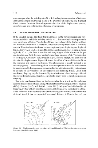
the miscible displacements. Figure 8.1 shows the effect of the mobility ratio M on
the formation and shape of the fingers. This phenomenon is usually referred to as
viscous fingering. The terminology is an accurate representation of the phenomenon
in macroscopically-homogeneous porous media, for which the mobility ratio reduces
to the ratio of the viscosities of the displaced and displacing fluids. Under field
conditions, fingering may be dominated by the distribution of the heterogeneities of
the porous formation and, therefore, one should simply refer to the phenomenon as
fingering.
Due to its significance, fingering has been studied for a long time. Several older
reviewsdiscussedthissubject, amongwhicharethoseofWoodingandMorel-Seytoux
(1976), Homsy (1987), and Sahimi (1993a, 1995). Many of the initial studies of
fingering, in flow of both miscible and immiscible fluids, were carried out in a Hele-
Shaw cell which is an essentially two-dimensional system confined between two flat
plates of length L that are separated by a small distance b. Flow in this cell can
M = 2.40 M = 17.3
Figure 8.1. Displacement fronts for two values of the mobility ratio M. The injection point is the lower
left corner (after Habermann, 1960)