
Page 197 - Geology of Carbonate Reservoirs
P. 197
178 FRACTURED RESERVOIRS
B
Differential stress (MPa) Ductile behavior shows more
Failure by rupture after exceeding elastic limit
A
strain with less stress beyond
elastic limit
Strain %
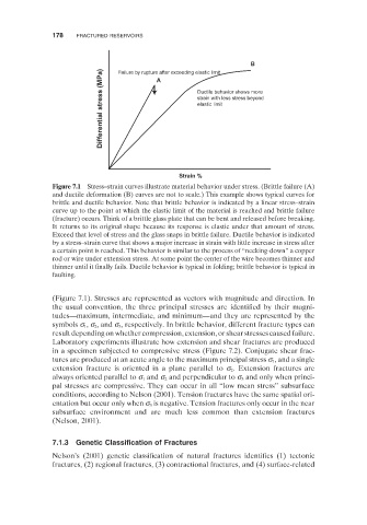
Figure 7.1 Stress – strain curves illustrate material behavior under stress. (Brittle failure (A)
and ductile deformation (B) curves are not to scale.) This example shows typical curves for
brittle and ductile behavior. Note that brittle behavior is indicated by a linear stress – strain
curve up to the point at which the elastic limit of the material is reached and brittle failure
(fracture) occurs. Think of a brittle glass plate that can be bent and released before breaking.
It returns to its original shape because its response is elastic under that amount of stress.
Exceed that level of stress and the glass snaps in brittle failure. Ductile behavior is indicated
by a stress – strain curve that shows a major increase in strain with little increase in stress after
a certain point is reached. This behavior is similar to the process of “ necking - down ” a copper
rod or wire under extension stress. At some point the center of the wire becomes thinner and
thinner until it finally fails. Ductile behavior is typical in folding; brittle behavior is typical in
faulting.
(Figure 7.1 ). Stresses are represented as vectors with magnitude and direction. In
the usual convention, the three principal stresses are identified by their magni-
tudes — maximum, intermediate, and minimum — and they are represented by the
, respectively. In brittle behavior, different fracture types can
symbols σ 1 , σ 2 , and σ 3
result depending on whether compression, extension, or shear stresses caused failure.
Laboratory experiments illustrate how extension and shear fractures are produced
in a specimen subjected to compressive stress (Figure 7.2 ). Conjugate shear frac-
, and a single
tures are produced at an acute angle to the maximum principal stress σ 1
. Extension fractures are
extension fracture is oriented in a plane parallel to σ 2
and only when princi-
always oriented parallel to σ 1 and σ 2 and perpendicular to σ 3
pal stresses are compressive. They can occur in all “ low mean stress ” subsurface
conditions, according to Nelson (2001) . Tension fractures have the same spatial ori-
is negative. Tension fractures only occur in the near
entation but occur only when σ 3
subsurface environment and are much less common than extension fractures
(Nelson, 2001 ).
7.1.3 Genetic Classification of Fractures
Nelson ’ s (2001) genetic classification of natural fractures identifies (1) tectonic
fractures, (2) regional fractures, (3) contractional fractures, and (4) surface - related