
Page 205 - Geology of Carbonate Reservoirs
P. 205
186 FRACTURED RESERVOIRS
Anticlinal Fold Monoclinal Flexure
150 m 50 m
A B
Listric Normal Fault Graben-in-Graben Normal Faults
50 m 150 m
C D
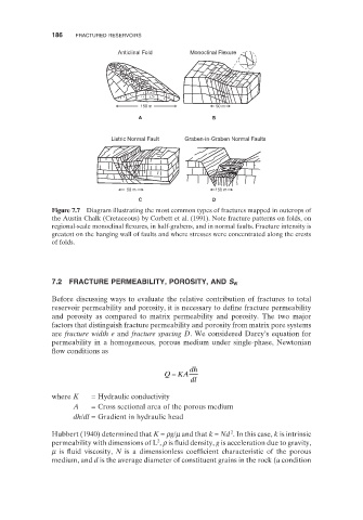
Figure 7.7 Diagram illustrating the most common types of fractures mapped in outcrops of
the Austin Chalk (Cretaceous) by Corbett et al. (1991) . Note fracture patterns on folds, on
regional - scale monoclinal flexures, in half - grabens, and in normal faults. Fracture intensity is
greatest on the hanging wall of faults and where stresses were concentrated along the crests
of folds.
7.2 FRACTURE PERMEABILITY, POROSITY, AND S W
Before discussing ways to evaluate the relative contribution of fractures to total
reservoir permeability and porosity, it is necessary to define fracture permeability
and porosity as compared to matrix permeability and porosity. The two major
factors that distinguish fracture permeability and porosity from matrix pore systems
are fracture width e and fracture spacing D . We considered Darcy ’ s equation for
permeability in a homogeneous, porous medium under single - phase, Newtonian
flow conditions as
=
QKA dh
dl
where K = Hydraulic conductivity
A = Cross sectional area of the porous medium
dh / dl = Gradient in hydraulic head
2
Hubbert (1940) determined that K = ρ g / μ and that k = Nd . In this case, k is intrinsic
2
permeability with dimensions of L , ρ is fluid density, g is acceleration due to gravity,
μ is fluid viscosity, N is a dimensionless coefficient characteristic of the porous
medium, and d is the average diameter of constituent grains in the rock (a condition