
Page 282 - Geothermal Energy Renewable Energy and The Environment
P. 282
The Geothermal Energy Future: Possibilities and Issues 273
1,200 500
1,000 Well separation 400
800
Well separation (m) 600 Volumetric flow 300 Volumetric flow (m 3 /hr)
200
400
100
200
0.0 0.0
0 50 100 150 200
Time (yrs)
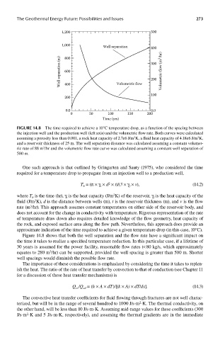
FIGUre 14.8 The time required to achieve a 10°C temperature drop, as a function of the spacing between
the injection well and the production well (left axis) and the volumetric flow rate. Both curves were calculated
assuming a porosity less than 0.001, a rock heat capacity of 2.7e6 J/m K, a fluid heat capacity of 4.18e6 J/m K,
3
3
and a reservoir thickness of 25 m. The well separation distance was calculated assuming a constant volumet-
ric rate of 88 m /hr and the volumetric flow rate curve was calculated assuming a constant well separation of
3
500 m.
One such approach is that outlined by Gringarten and Sauty (1975), who considered the time
required for a temperature drop to propagate from an injection well to a production well,
2
T = (π × γ × d × t)/(3 × γ × v), (14.2)
f
t
b
where T is the time (hr), γ is the heat capacity (J/m K) of the reservoir, γ is the heat capacity of the
3
f
t
b
fluid (J/m K), d is the distance between wells (m), t is the reservoir thickness (m), and v is the flow
3
rate (m /hr). This approach assumes constant temperatures on either side of the reservoir body, and
3
does not account for the change in conductivity with temperature. Rigorous representation of the rate
of temperature draw down also requires detailed knowledge of the flow geometry, heat capacity of
the rock, and exposed surface area along the flow path. Nevertheless, this approach does provide an
approximate indication of the time required to achieve a given temperature drop (in this case, 10°C).
Figure 14.8 shows that both the well separation and the flow rate have a significant impact on
the time it takes to realize a specified temperature reduction. In this particular case, if a lifetime of
30 years is assumed for the power facility, reasonable flow rates (< 80 kg/s, which approximately
equates to 280 m /hr) can be supported, provided the well spacing is greater than 500 m. Shorter
3
well spacings would diminish the possible flow rate.
The importance of these considerations is emphasized by considering the time it takes to replen-
ish the heat. The ratio of the rate of heat transfer by convection to that of conduction (see Chapter 11
for a discussion of these heat transfer mechanisms) is
Q /Q = (h × A × dT)/[(k × A) × dT/dx]. (14.3)
cd
cv
The convective heat transfer coefficients for fluid flowing through fractures are not well charac-
2
terized, but will be in the range of several hundred to 1000 J/s-m -K. The thermal conductivity, on
the other hand, will be less than 10 J/s-m-K. Assuming mid-range values for these coefficients (300
2
J/s-m -K and 5 J/s-m-K, respectively), and assuming the thermal gradients are in the immediate