
Page 279 - Geothermal Energy Renewable Energy and The Environment
P. 279
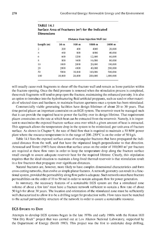
270                          Geothermal Energy: Renewable Energy and the Environment


                           Table 14.1
                           surface area of Fractures (m ) for the Indicated
                                                    2
                           dimensions
                                              distance from Injection well (m)
                           length (m)   50 m     100 m    1000 m     5000 m
                           2              200      400      4000      20,000
                           4              400      800      8000      40,000
                           6              600     1200     12,000     60,000
                           8              800     1600     16,000     80,000
                           10            1000     2000     20,000    100,000
                           20            2000     4000     40,000    200,000
                           50            5000    10,000   100,000    500,000
                           100          10,000   20,000   200,000   1,000,000


            will usually cause rock fragments to shear off the fracture wall and remain as loose particles within
            the fracture opening. Once the fluid pressure is removed when the stimulation process is completed,
            these rock fragments will tend to prop open the fracture, maintaining the enhanced porosity. It is also
            an option to introduce into the hydrofracturing fluid artificial proppants, such as sand or other materi-
            als of selected sizes and hardness, to maintain fracture apertures once a system has been stimulated.
              Commercially viable generating facilities have design lifetimes of about 20 to 30 years. That
            time period places an important constraint on an EGS system. The reservoir must be managed such
            that it can provide the required heat to power the facility over its design lifetime. That requirement
            places constraints on the rate at which heat can be extracted from the reservoir. Namely, it is impor-
            tant to maximize the exposed fracture surface area over which a given amount of heat is extracted.
            This approach allows the temperature drop in the system to be minimized, per unit area of fracture
            surface. As shown in Chapter 9, the rate of fluid flow that is required to maintain a 50 MW power
            plant where the resource temperature is in the range of 200–250°C is on the order of 50 kg/s.
              Table 14.1 lists the exposed surface areas of rectangular fractures that have propagated the indi-
            cated distance from the well, and that have the stipulated length perpendicular to that direction.
                                                                                2
            Armstead and Tester (1987) have shown that surface areas on the order of 100,000 m  per fracture
            are required at these flow rates in order to keep the temperature drop along the fracture surface
            small enough to assure adequate reservoir heat for the required lifetime. Clearly, this stipulation
            requires that the ideal situation to maintain a long-lived thermal reservoir is that stimulation result
            in a few fractures that propagate over significant distances.
              Natural fractures are, however, more likely to have complex dimensional characteristics and form
            cross-cutting networks, than evolve as simple planar features. A network geometry can result in a func-
            tional system, provided the permeability along flow paths is adequate. Such networks must have fracture
            permeabilities on the order of 10 to 50 md in order to sustain adequate flow for power generation.
              In summary, the necessary features of a sustainable EGS system are that a stimulated zone
              volume of about a few km  must have a fracture network sufficient to sustain a flow rate of about
                                 3
            50 kg/s for about 30 years. The location and orientation of the stimulated zone must be sufficiently
            well characterized to allow it to be a drilling target for production wells. Flow rates must be matched
            to the actual permeability structure of the network in order to assure a sustainable resource.


            eGs efforTs To daTe
            Attempts to develop EGS systems began in the late 1970s and early 1980s with the Fenton Hill
            “Hot Dry Rock” project that was carried out at Los Alamos National Laboratory, supported by
            the  Department  of  Energy  (Smith  1983).  This  project  was  the  first  to  undertake  deep  drilling,