
Page 52 - Geothermal Energy Renewable Energy and The Environment
P. 52
Thermodynamics and Geothermal Systems 35
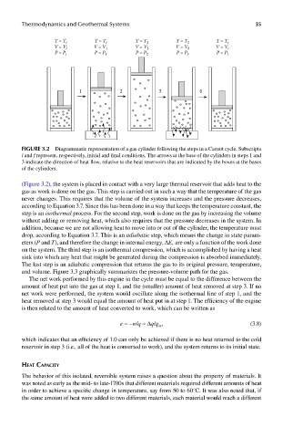
T = T i T = T i T = T 2 T = T 2 T = T i
V = V i V = V 1 V = V 2 V = V 3 V = V i
P = P i P = P 1 P = P 2 P = P 3 P = P i
1 2 3 4
FIGUre 3.2 Diagrammatic representation of a gas cylinder following the steps in a Carnot cycle. Subscripts
i and f represent, respectively, initial and final conditions. The arrows at the base of the cylinders in steps 1 and
3 indicate the direction of heat flow, relative to the heat reservoirs that are indicated by the boxes at the bases
of the cylinders.
(Figure 3.2), the system is placed in contact with a very large thermal reservoir that adds heat to the
gas as work is done on the gas. This step is carried out in such a way that the temperature of the gas
never changes. This requires that the volume of the system increases and the pressure decreases,
according to Equation 3.7. Since this has been done in a way that keeps the temperature constant, the
step is an isothermal process. For the second step, work is done on the gas by increasing the volume
without adding or removing heat, which also requires that the pressure decreases in the system. In
addition, because we are not allowing heat to move into or out of the cylinder, the temperature must
drop, according to Equation 3.7. This is an adiabatic step, which means the change in state param-
eters (P and T), and therefore the change in internal energy, ΔE, are only a function of the work done
on the system. The third step is an isothermal compression, which is accomplished by having a heat
sink into which any heat that might be generated during the compression is absorbed immediately.
The last step is an adiabatic compression that returns the gas to its original pressure, temperature,
and volume. Figure 3.3 graphically summarizes the pressure-volume path for the gas.
The net work performed by this engine in the cycle must be equal to the difference between the
amount of heat put into the gas at step 1, and the (smaller) amount of heat removed at step 3. If no
net work were performed, the system would oscillate along the isothermal line of step 1, and the
heat removed at step 3 would equal the amount of heat put in at step 1. The efficiency of the engine
is then related to the amount of heat converted to work, which can be written as
e = –w/q = Δq/q , (3.8)
in
which indicates that an efficiency of 1.0 can only be achieved if there is no heat returned to the cold
reservoir in step 3 (i.e., all of the heat is converted to work), and the system returns to its initial state.
heaT capaciTy
The behavior of this isolated, reversible system raises a question about the property of materials. It
was noted as early as the mid- to late-1700s that different materials required different amounts of heat
in order to achieve a specific change in temperature, say from 50 to 60°C. It was also noted that, if
the same amount of heat were added to two different materials, each material would reach a different