
Page 57 - Geothermal Energy Renewable Energy and The Environment
P. 57
40 Geothermal Energy: Renewable Energy and the Environment
500
99.6°C 179.9°C
0 Liquid, 1.0 MPa
–500
H–T × S (kJ/kmole) –1,000 Liquid, 0.1 MPa
Vapor, 0.1MPa
–1,500
Vapor, 1.0 MPa
–2,000
–2,500
0 50 100 150 200 250 300
Temperature (°C)
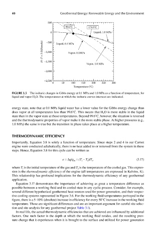
FIGUre 3.5 The isobaric changes in Gibbs energy at 0.1 MPa and 1.0 MPa as a function of temperature, for
liquid and vapor H 2 O. The temperatures at which the isobaric curves intersect are indicated.
energy state, note that at 0.1 MPa liquid water has a lower value for the Gibbs energy change than
does vapor at all temperatures less than 99.6°C. This means that H O is more stable in the liquid
2
state than in the vapor state at these temperatures. Beyond 99.6°C, however, the situation is reversed
and the thermodynamic properties of vapor make it the more stable phase. At higher pressures (e.g.,
1.0 MPa) the same is true but the transition in phase takes place at a higher temperature.
ThermodynamIc eFFIcIency
Importantly, Equation 3.8 is solely a function of temperature. Since steps 2 and 4 in our Carnot
engine were conducted adiabatically, there is no heat added to or removed from the system in these
steps. Hence, Equation 3.8 for this cycle can be written as
e = Δq/q = (T – T )/T , (3.17)
in
2
i
i
where T is the initial temperature of the gas and T is the temperature of the cooled gas. This expres-
2
i
sion is the thermodynamic efficiency of the engine (all temperatures are expressed in Kelvins, K).
This relationship has profound implications for the thermodynamic efficiency of any geothermal
application.
Equation 3.17 demonstrates the importance of achieving as great a temperature difference as
possible between a working fluid and its cooled state in any cyclic process. Consider, for example,
several different hypothetical geothermal heat sources used for power generation, and their respec-
tive cooling systems represented in Figure 3.6. For the working fluid temperatures portrayed in the
figure, there is a 5–10% (absolute) increase in efficiency for every 50°C increase in the working fluid
temperature. These are significant differences and are an important argument for careful site selec-
tion and site analysis for any geothermal project Table 3.1).
In real life, the actual thermodynamic efficiencies that are achieved are influenced by additional
factors. One such factor is the depth at which the working fluid resides, and the resulting pres-
sure change that it experiences when it is brought to the surface and utilized for power generation