
Page 155 - Geothermal Energy Systems Exploration, Development, and Utilization
P. 155
3.4 Casing and Cementation 131
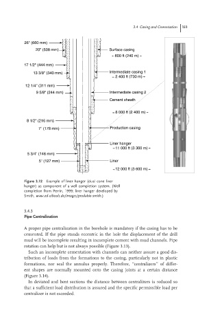
26" (660 mm)
20" (508 mm) Surface casing
800 ft (240 m)
17 1/2" (444 mm)
13 3/8" (340 mm) Intermediate casing 1
2 400 ft (730 m)
12 1/4" (311 mm)
9 5/8" (244 mm) Intermediate casing 2
Cement sheath
8 000 ft (2 400 m)
8 1/2" (216 mm)
7" (178 mm) Production casing
Liner hanger
11 000 ft (3 300 m)
5 3/4" (146 mm)
5" (127 mm) Liner
12 000 ft (3 600 m)
Figure 3.12 Example of liner hanger (dual cone liner
hanger) as component of a well completion system. (Well
completion from Perrin, 1999; liner hanger developed by
Smith, www.ed-oiltools.de/images/produkte-smith.)
3.4.3
Pipe Centralization
A proper pipe centralization in the borehole is mandatory if the casing has to be
cemented. If the pipe stands eccentric in the hole the displacement of the drill
mud will be incomplete resulting in incomplete cement with mud channels. Pipe
rotation can help but is not always possible (Figure 3.13).
Such an incomplete cementation with channels can neither assure a good dis-
tribution of loads from the formations to the casing, particularly not in plastic
formations, nor seal the annulus properly. Therefore, ‘‘centralizers’’ of differ-
ent shapes are normally mounted onto the casing joints at a certain distance
(Figure 3.14).
In deviated and bent sections the distance between centralizers is reduced so
that a sufficient load distribution is assured and the specific permissible load per
centralizer is not exceeded.