
Page 185 - Geothermal Energy Systems Exploration, Development, and Utilization
P. 185
3.9 Case Study Groß Sch¨ onebeck Well 161
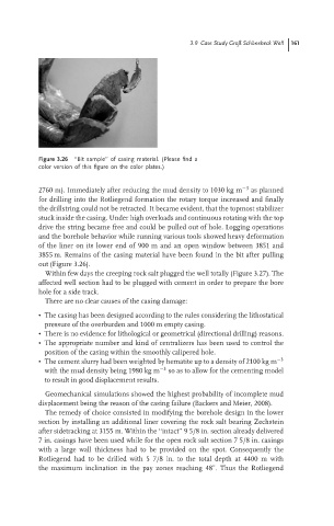
Figure 3.26 ‘‘Bit sample’’ of casing material. (Please find a
color version of this figure on the color plates.)
2760 m). Immediately after reducing the mud density to 1030 kg m −3 as planned
for drilling into the Rotliegend formation the rotary torque increased and finally
the drillstring could not be retracted. It became evident, that the topmost stabilizer
stuck inside the casing. Under high overloads and continuous rotating with the top
drive the string became free and could be pulled out of hole. Logging operations
and the borehole behavior while running various tools showed heavy deformation
of the liner on its lower end of 900 m and an open window between 3851 and
3855 m. Remains of the casing material have been found in the bit after pulling
out (Figure 3.26).
Within few days the creeping rock salt plugged the well totally (Figure 3.27). The
affected well section had to be plugged with cement in order to prepare the bore
hole for a side track.
There are no clear causes of the casing damage:
• The casing has been designed according to the rules considering the lithostatical
pressure of the overburden and 1000 m empty casing.
• There is no evidence for lithological or geometrical (directional drilling) reasons.
• The appropriate number and kind of centralizers has been used to control the
position of the casing within the smoothly calipered hole.
• The cement slurry had been weighted by hematite up to a density of 2100 kg m −3
with the mud density being 1980 kg m −3 so as to allow for the cementing model
to result in good displacement results.
Geomechanical simulations showed the highest probability of incomplete mud
displacement being the reason of the casing failure (Backers and Meier, 2008).
The remedy of choice consisted in modifying the borehole design in the lower
section by installing an additional liner covering the rock salt bearing Zechstein
after sidetracking at 3155 m. Within the ‘‘intact’’ 9 5/8 in. section already delivered
7 in. casings have been used while for the open rock salt section 7 5/8 in. casings
with a large wall thickness had to be provided on the spot. Consequently the
Rotliegend had to be drilled with 5 7/8 in. to the total depth at 4400 m with
◦
the maximum inclination in the pay zones reaching 48 . Thus the Rotliegend