
Page 127 - Global Tectonics
P. 127
114 CHAPTER 5
Figure 5.20 Ridge (R)–trench (T)–transform fault (F)–triple junction between plates, A, B, and C.
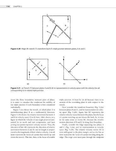
Figure 5.21 (a) Trench (T) between plates A and B; (b) its representation in velocity space with the velocity line ab
corresponding to its related triple junction.
down the three boundaries between pairs of plates. triple junction. B must lie on ab because there is no
It is easier to visualize the conditions for stability of motion of the overriding plate B with respect to the
the triple junction if each boundary is fi rst considered trench.
individually. Now consider the transform boundary (Fig. 5.22a)
Figure 5.21a shows the trench, at which plate A is between plates B and C, and its representation in veloc-
underthrusting plate B in a northeasterly direction. ity space (Fig. 5.22b). Again, line BC represents the
Figure 5.21b shows the relative movement between A relative velocity vector between the plates, but the locus
and B in velocity space (Cox & Hart, 1986), that is, on a of a point traveling up and down the fault, bc, is now
figure in which the velocity of any single point is repre- in the same sense as vector BC, because the relative
sented by its north and east components, and lines motion direction of B and C is along their boundary.
joining two points represent velocity vectors. Thus, the Finally, consider the ridge separating two plates A
direction of line AB represents the direction of relative and C (Fig. 5.23a), and its representation in velocity
movement between A and B, and its length is propor- space (Fig. 5.23b). The relative velocity vector AC is
tional to the magnitude of their relative velocity. Line ab now orthogonal to the plate margin, and so the line ac
must represent the locus of a point that travels up and now represents the locus of a point traveling along the
down the trench. This line, then, is the locus of a stable ridge. The ridge crest must pass through the midpoint