
Page 30 - Global Tectonics
P. 30
THE INTERIOR OF THE EARTH 17
thus giving an indication of the stress field giving rise
to the earthquake (Fig. 2.10c) (Section 2.10.2).
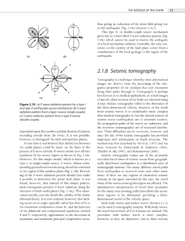
This type II, or double-couple source mechanism
gives rise to a four-lobed S wave radiation pattern (Fig.
2.10c) which cannot be used to resolve the ambiguity
of a focal mechanism solution. Generally, the only con-
straint on the identity of the fault plane comes from a
consideration of the local geology in the region of the
earthquake.
2.1.8 Seismic tomography
Tomography is a technique whereby three-dimensional
images are derived from the processing of the inte-
grated properties of the medium that rays encounter
along their paths through it. Tomography is perhaps
best known in its medical applications, in which images
of specific plane sections of the body are obtained using
Figure 2.10 (a) P wave radiation pattern for a type I X-rays. Seismic tomography refers to the derivation of
and type II earthquake source mechanism; (b) S wave the three-dimensional velocity structure of the Earth
radiation pattern from a type I source (single couple); from seismic waves. It is considerably more complex
(c) S wave radiation pattern from a type II source than medical tomography in that the natural sources of
(double couple). seismic waves (earthquakes) are of uncertain location,
the propagation paths of the waves are unknown, and
the receivers (seismographs) are of restricted distribu-
dependent upon the number and distribution of stations tion. These diffi culties can be overcome, however, and
recording arrivals from the event. It is not possible, since the late 1970s seismic tomography has provided
however, to distinguish the fault and auxiliary planes. important new information on Earth structure. The
At one time it was believed that distinction between method was first described by Aki et al. (1977) and has
the nodal planes could be made on the basis of the been reviewed by Dziewonski & Anderson (1984),
pattern of S wave arrivals. P waves radiate into all four Thurber & Aki (1987), and Romanowicz (2003).
quadrants of the source region as shown in Fig. 2.10a. Seismic tomography makes use of the accurately
However, for this simple model, which is known as a recorded travel times of seismic waves from geograph-
type I, or single-couple source, S waves, whose corre- ically distributed earthquakes at a distributed suite of
sponding ground motion is shearing, should be restricted seismograph stations. The many different travel paths
to the region of the auxiliary plane (Fig. 2.10b). Record- from earthquakes to receivers cross each other many
ing of the S wave radiation pattern should then make times. If there are any regions of anomalous seismic
it possible to determine the actual fault plane. It was velocity in the space traversed by the rays, the travel
found, however, that instead of this simple pattern, times of the waves crossing this region are affected. The
most earthquakes produce S wave radiation along the simultaneous interpretation of travel time anomalies
direction of both nodal planes (Fig. 2.10c). This obser- for the many criss-crossing paths then allows the anom-
vation initially cast into doubt the validity of the elastic alous regions to be delineated, providing a three-
rebound theory. It is now realized, however, that fault- dimensional model of the velocity space.
ing occurs at an angle, typically rather less than 45% to Both body waves and surface waves (Section 2.1.3)
the maximum compressive stress, σ 1 , and the bisectors can be used in tomography analysis. With body waves,
of the dilational and compressional quadrants, termed the actual travel times of P or S phases are utilized. The
P and T, respectively, approximate to the directions of procedure with surface waves is more complex,
maximum and minimum principal compressive stress, however, as they are dispersive; that is, their velocity