
Page 26 - Global Tectonics
P. 26
THE INTERIOR OF THE EARTH 13
Compression
Nodal plane
Auxiliary Dilation
plane
Fault plane Focal sphere
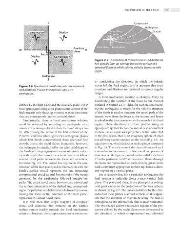
Figure 2.5 Distribution of compressional and dilational
first arrivals from an earthquake on the surface of a
spherical Earth in which seismic velocity increases with
depth.
by considering the directions in which the seismic
Figure 2.4 Quadrantal distribution of compressional waves left the focal region, as it is apparent that com-
and dilational P wave first motions about an pressions and dilations are restricted to certain angular
earthquake. ranges.
A focal mechanism solution is obtained fi rstly by
determining the location of the focus by the method
defined by the fault plane and the auxiliary plane. No P outlined in Section 2.1.4. Then, for each station record-
waves propagate along these planes as movement of the ing the earthquake, a model for the velocity structure
fault imparts only shearing motions in their directions; of the Earth is used to compute the travel path of the
they are consequently known as nodal planes. seismic wave from the focus to the station, and hence
Simplistically, then, a focal mechanism solution to calculate the direction in which the wave left the focal
could be obtained by recording an earthquake at a region. These directions are then plotted, using an
number of seismographs distributed around its epicen- appropriate symbol for compressional or dilational fi rst
ter, determining the nature of the first motions of the motion, on an equal area projection of the lower half
P waves, and then selecting the two orthogonal planes of the focal sphere, that is, an imaginary sphere of small
which best divide compressional from dilational fi rst but arbitrary radius centered on the focus (Fig. 2.5). An
arrivals, that is, the nodal planes. In practice, however, equal area net, which facilitates such a plot, is illustrated
the technique is complicated by the spheroidal shape of in Fig. 2.6. The scale around the circumference of such
the Earth and the progressive increase of seismic veloc- a net refers to the azimuth, or horizontal component of
ity with depth that causes the seismic waves to follow direction, while dips are plotted on the radial scale from
curved travel paths between the focus and recorders. 0° at the perimeter to 90° at the center. Planes through
Consider Fig. 2.5. The dotted line represents the con- the focus are represented on such plots by great circles
tinuation of the fault plane, and its intersection with the with a curvature appropriate to their dip; hence a diam-
Earth’s surface would represent the line separating eter represents a vertical plane.
compressional and dilational first motions if the waves Let us assume that, for a particular earthquake, the
generated by the earthquake followed straight-line fault motion is strike-slip along a near vertical fault
paths. The actual travel paths, however, are curved and plane. This plane and the auxiliary plane plot as orthog-
the surface intersection of the dashed line, correspond- onal great circles on the projection of the focal sphere,
ing to the path that would have been followed by a wave as shown on Fig. 2.7. The lineation defined by the inter-
leaving the focus in the direction of the fault plane, section of these planes is almost vertical, so it is appar-
represents the actual nodal plane. ent that the direction of movement along the fault is
It is clear then, that simple mapping of compres- orthogonal to this intersection, that is, near horizontal.
sional and dilational first motions on the Earth’s The two shaded and two unshaded regions of the pro-
surface cannot readily provide the focal mechanism jection defined by the nodal planes now correspond to
solution. However, the complications can be overcome the directions in which compressional and dilational