
Page 119 - Glucose Monitoring Devices
P. 119
120 CHAPTER 6 CGM sensor technology
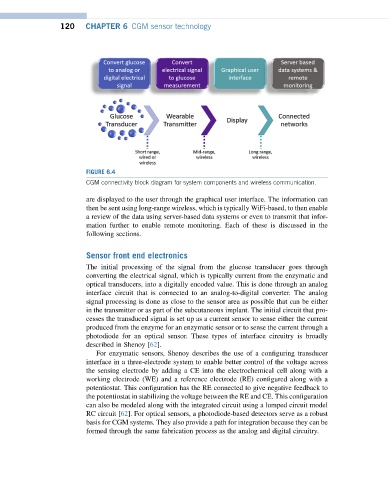
FIGURE 6.4
CGM connectivity block diagram for system components and wireless communication.
are displayed to the user through the graphical user interface. The information can
then be sent using long-range wireless, which is typically WiFi-based, to then enable
a review of the data using server-based data systems or even to transmit that infor-
mation further to enable remote monitoring. Each of these is discussed in the
following sections.
Sensor front end electronics
The initial processing of the signal from the glucose transducer goes through
converting the electrical signal, which is typically current from the enzymatic and
optical transducers, into a digitally encoded value. This is done through an analog
interface circuit that is connected to an analog-to-digital converter. The analog
signal processing is done as close to the sensor area as possible that can be either
in the transmitter or as part of the subcutaneous implant. The initial circuit that pro-
cesses the transduced signal is set up as a current sensor to sense either the current
produced from the enzyme for an enzymatic sensor or to sense the current through a
photodiode for an optical sensor. These types of interface circuitry is broadly
described in Shenoy [62].
For enzymatic sensors, Shenoy describes the use of a configuring transducer
interface in a three-electrode system to enable better control of the voltage across
the sensing electrode by adding a CE into the electrochemical cell along with a
working electrode (WE) and a reference electrode (RE) configured along with a
potentiostat. This configuration has the RE connected to give negative feedback to
the potentiostat in stabilizing the voltage between the RE and CE. This configuration
can also be modeled along with the integrated circuit using a lumped circuit model
RC circuit [62]. For optical sensors, a photodiode-based detectors serve as a robust
basis for CGM systems. They also provide a path for integration because they can be
formed through the same fabrication process as the analog and digital circuitry.