
Page 120 - Glucose Monitoring Devices
P. 120
Sensor interface and system connectivity 121
Further integration of the system-level functionality also enables scaling of the
systems overall footprint as well as the detector size itself. This integration can build
in circuitry to digitize the signal on-site to minimize the opportunity of introducing
other noise sources into the system. Analog-to-digital converters can be imple-
mented in the same transistor-based, integrated circuits as the potentiostat.
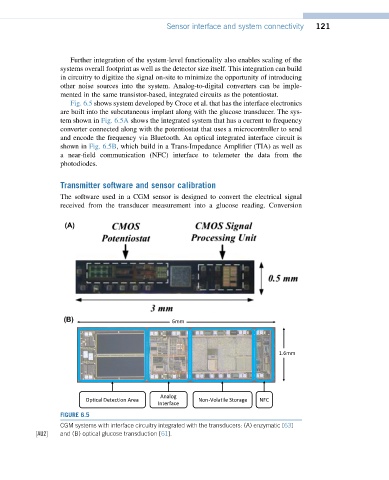
Fig. 6.5 shows system developed by Croce et al. that has the interface electronics
are built into the subcutaneous implant along with the glucose transducer. The sys-
tem shown in Fig. 6.5A shows the integrated system that has a current to frequency
converter connected along with the potentiostat that uses a microcontroller to send
and encode the frequency via Bluetooth. An optical integrated interface circuit is
shown in Fig. 6.5B, which build in a Trans-Impedance Amplifier (TIA) as well as
a near-field communication (NFC) interface to telemeter the data from the
photodiodes.
Transmitter software and sensor calibration
The software used in a CGM sensor is designed to convert the electrical signal
received from the transducer measurement into a glucose reading. Conversion
(A)
6mm
(B)
1.6mm
Analog
Optical Detection Area Non-Volatile Storage NFC
Interface
FIGURE 6.5
CGM systems with interface circuitry integrated with the transducers: (A) enzymatic [63]
½AU2 and (B) optical glucose transduction [61].