
Page 304 - HVAC Pump Handbook
P. 304
Rishel_CH10.qxd 21/4/06 6:20 PM Page 301
Basics of Pump Application for HVAC Systems
Basics of Pump Application for HVAC Systems 301
Supply power
Flow meter
VFD
Watt transmitter VFD
Control
in control center
Control center
with variable
speed drives
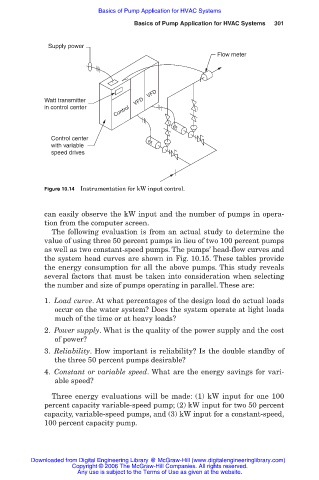
Figure 10.14 Instrumentation for kW input control.
can easily observe the kW input and the number of pumps in opera-
tion from the computer screen.
The following evaluation is from an actual study to determine the
value of using three 50 percent pumps in lieu of two 100 percent pumps
as well as two constant-speed pumps. The pumps’ head-flow curves and
the system head curves are shown in Fig. 10.15. These tables provide
the energy consumption for all the above pumps. This study reveals
several factors that must be taken into consideration when selecting
the number and size of pumps operating in parallel. These are:
1. Load curve. At what percentages of the design load do actual loads
occur on the water system? Does the system operate at light loads
much of the time or at heavy loads?
2. Power supply. What is the quality of the power supply and the cost
of power?
3. Reliability. How important is reliability? Is the double standby of
the three 50 percent pumps desirable?
4. Constant or variable speed. What are the energy savings for vari-
able speed?
Three energy evaluations will be made: (1) kW input for one 100
percent capacity variable-speed pump; (2) kW input for two 50 percent
capacity, variable-speed pumps, and (3) kW input for a constant-speed,
100 percent capacity pump.
Downloaded from Digital Engineering Library @ McGraw-Hill (www.digitalengineeringlibrary.com)
Copyright © 2006 The McGraw-Hill Companies. All rights reserved.
Any use is subject to the Terms of Use as given at the website.