
Page 48 - HVAC Pump Handbook
P. 48
Rishel_CH03.qxd 21/4/06 6:07 PM Page 45
Piping System Friction
Piping System Friction 45
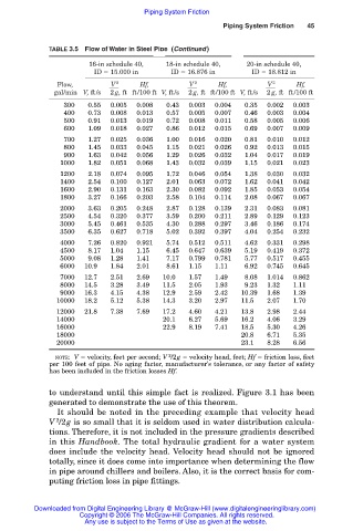
TABLE 3.5 Flow of Water in Steel Pipe (Continued )
16-in schedule 40, 18-in schedule 40, 20-in schedule 40,
ID 15.000 in ID 16.876 in ID 18.812 in
V
Flow, 2 Hf, 2 Hf, 2 Hf,
V
V
gal/min V, ft/s 2 g, ft ft/100 ft V, ft/s 2 g, ft ft/100 ft V, ft/s 2 g, ft ft/100 ft
00300 00.55 0.005 0.008 00.43 0.003 0.004 00.35 0.002 0.003
00400 00.73 0.008 0.013 00.57 0.005 0.007 00.46 0.003 0.004
00500 00.91 0.013 0.019 00.72 0.008 0.011 00.58 0.005 0.006
00600 01.09 0.018 0.027 00.86 0.012 0.015 00.69 0.007 0.009
00700 01.27 0.025 0.036 01.00 0.016 0.020 00.81 0.010 0.012
00800 01.45 0.033 0.045 01.15 0.021 0.026 00.92 0.013 0.015
00900 01.63 0.042 0.056 01.29 0.026 0.032 01.04 0.017 0.019
01000 01.82 0.051 0.068 01.43 0.032 0.039 01.15 0.021 0.023
01200 02.18 0.074 0.095 01.72 0.046 0.054 01.38 0.030 0.032
01400 02.54 0.100 0.127 02.01 0.063 0.072 01.62 0.041 0.042
01600 02.90 0.131 0.163 02.30 0.082 0.092 01.85 0.053 0.054
01800 03.27 0.166 0.203 02.58 0.104 0.114 02.08 0.067 0.067
02000 03.63 0.205 0.248 02.87 0.128 0.139 02.31 0.083 0.081
02500 04.54 0.320 0.377 03.59 0.200 0.211 02.89 0.129 0.123
03000 05.45 0.461 0.535 04.30 0.288 0.297 03.46 0.186 0.174
03500 06.35 0.627 0.718 05.02 0.392 0.397 04.04 0.254 0.232
04000 07.26 0.820 0.921 05.74 0.512 0.511 04.62 0.331 0.298
04500 08.17 1.04 1.15 06.45 0.647 0.639 05.19 0.419 0.372
05000 09.08 1.28 1.41 07.17 0.799 0.781 05.77 0.517 0.455
06000 10.9 1.84 2.01 08.61 1.15 1.11 06.92 0.745 0.645
07000 12.7 2.51 2.69 10.0 1.57 1.49 08.08 1.014 0.862
08000 14.5 3.28 3.49 11.5 2.05 1.93 09.23 1.32 1.11
09000 16.3 4.15 4.38 12.9 2.59 2.42 10.39 1.68 1.39
10000 18.2 5.12 5.38 14.3 3.20 2.97 11.5 2.07 1.70
12000 21.8 7.38 7.69 17.2 4.60 4.21 13.8 2.98 2.44
14000 20.1 6.27 5.69 16.2 4.06 3.29
16000 22.9 8.19 7.41 18.5 5.30 4.26
18000 20.8 6.71 5.35
20000 23.1 8.28 6.56
2
NOTE: V velocity, feet per second; V /2g velocity head, feet; Hf friction loss, feet
per 100 feet of pipe. No aging factor, manufacturer’s tolerance, or any factor of safety
has been included in the friction losses Hf.
to understand until this simple fact is realized. Figure 3.1 has been
generated to demonstrate the use of this theorem.
It should be noted in the preceding example that velocity head
V /2g is so small that it is seldom used in water distribution calcula-
2
tions. Therefore, it is not included in the pressure gradients described
in this Handbook. The total hydraulic gradient for a water system
does include the velocity head. Velocity head should not be ignored
totally, since it does come into importance when determining the flow
in pipe around chillers and boilers. Also, it is the correct basis for com-
puting friction loss in pipe fittings.
Downloaded from Digital Engineering Library @ McGraw-Hill (www.digitalengineeringlibrary.com)
Copyright © 2006 The McGraw-Hill Companies. All rights reserved.
Any use is subject to the Terms of Use as given at the website.