
Page 131 - Hacking Roomba
P. 131
112 Part I — Interfacing
Optoisolator: Remote Controls, Virtual Wall, and Dock
The emitter in an optoisolator is usually an infrared LED and the detector is a matching
infrared phototransistor or photodiode. The first type shown in Figure 6-3 is an optoisolator.
The light from the LED travels unobstructed to the detector. Optoisolators are used to
separate circuits that would be too dangerous or too physically far apart to connect electrically.
Common optoisolator uses are motor driver circuits (to separate high-power circuits from low-
power circuits) and remote controls for TVs and stereos. You could also consider the high-
speed fiber optic links that drive the Internet as a type of optoisolator. In the case of Roomba,
the clear circular bump on the front top is the detector half of an optoisolator. It receives
remote control commands and “sees” the virtual wall and docking base.
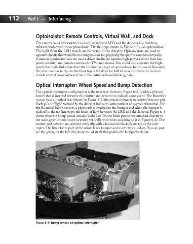
Optical Interrupter: Wheel Speed and Bump Detection
The optical interrupter configuration is the next type shown in Figure 6-3. It adds a physical
barrier that is inserted between the emitter and detector to indicate some event. The Roomba’s
motors have a toothed disc (shown in Figure 5-2) that rotates between an emitter/detector pair.
Each pulse of light received by the detector indicates some number of degrees of rotation. For
the Roomba’s bump sensors, a plastic tab is attached to the bumper and when the bumper is
pushed in, the tab interrupts the beam of light between the LED and the detector. Figure 6-4
shows what the bump sensor actually looks like. It’s the black plastic box attached directly to
the main green circuit board (oriented vertically with wires attaching to it in Figure 6-4). The
emitter and detector are oriented vertically, with a horizontal black plastic tab as the inter-
rupter. The black tab is part of the whole black bumper and moves when it does. You can just
see the spring on the left (the shiny coil of steel) that pushes the bumper back out.
FIGURE 6-4: Bump sensor, an optical interrupter