
Page 415 - Hacking Roomba
P. 415
396 Appendix A — Soldering and Safety Basics
Testing
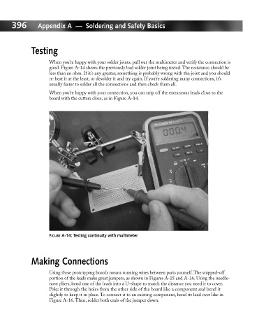
When you’re happy with your solder joints, pull out the multimeter and verify the connection is
good. Figure A-14 shows the previously bad solder joint being tested. The resistance should be
less than an ohm. If it’s any greater, something is probably wrong with the joint and you should
re-heat it at the least, or desolder it and try again. If you’re soldering many connections, it’s
usually faster to solder all the connections and then check them all.
When you’re happy with your connection, you can snip off the extraneous leads close to the
board with the cutters close, as in Figure A-14.
FIGURE A-14: Testing continuity with multimeter
Making Connections
Using these prototyping boards means running wires between parts yourself. The snipped-off
portion of the leads make great jumpers, as shown in Figures A-15 and A-16. Using the needle-
nose pliers, bend one of the leads into a U-shape to match the distance you need it to cover.
Poke it through the holes from the other side of the board like a component and bend it
slightly to keep it in place. To connect it to an existing component, bend its lead over like in
Figure A-16. Then, solder both ends of the jumper down.