
Page 129 - Handbook Of Multiphase Flow Assurance
P. 129
Hydrate of natural gas 125
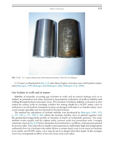
FIG. 5.19 Cr 13 steel without and with hydrate formation. Photo by Yuri Makogon.
Cr 13 steel, as illustrated in Fig. 5.19, also shows higher corrosion rate with hydrate forma-
tion (Makogon, 1999; Makogon and Makogon, 2004; Makogon et al., 2000).
Gas hydrate in wells and in nature
Stability of naturally occurring gas hydrates in wells and in natural settings such as in
seabed, in permafrost and other locations is important in evaluation of seafloor stability and
drilling through hydrate-saturated zones. This method of hydrate stability evaluation is also
useful for subsea wells in checking whether the setting depth for a SCSSV safety valve is
sufficient to avoid hydrate formation during a prolonged well shut-in so that the safety valve
could remain operable and not blocked by formed hydrate.
The method for calculation of hydrate stability was developed by Makogon (1965, 1974
p. 151, 1981 p. 171, 1982 p. 303) where the hydrate stability curve is plotted together with
the geothermal temperature profile as function of depth or hydrostatic pressure. The same
method works equally well for subsea wells, onshore wells and permafrost soils. Example
schematic chart in Fig. 5.20 below illustrates that method for a wellbore, with pressure plotted
in reverse order. This chart shows depths where pressure is sufficiently high and temperature
sufficiently low for a hydrate to be stable. Below a certain depth, rock is too warm for hydrate
to be stable, and SCSSV safety valve may be set at or deeper than that depth. In the example
chart this corresponds to 900 m where two lines cross each other.