
Page 340 - Handbook Of Multiphase Flow Assurance
P. 340
Computer modeling of interaction between a hydrate surface and an inhibitor 339
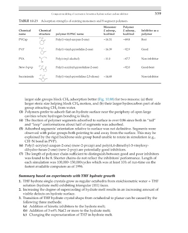
TABLE 10.23 Adsorption strengths of existing monomers and 8-segment polymers.
Monomer Polymer
Chemical Chemical E adsorp., E adsorp., Inhibitor as a
name structure polymer IUPAC name kcal/mol kcal/mol polymer
PVCap Poly(1-vinyl-azepan-2-one) −16.31 −69.8 Best
PVP Poly(1-vinyl-pyrrolidin-2-one) −16.39 −92.9 Good
PVA Poly(vinyl-alcohol) −11.0 −67.7 Non-inhibitor
New-3-pvp Poly(1-acryloyl-pyrrolidine-2-one) −92.0 Good-best
Succinimide Poly(1-vinyl-pyrrolidine-2,5-dione) −14.68 Non-inhibitor
larger side groups block CH 4 adsorption better (Fig. 10.88) for two reasons: (a) their
larger steric size helping block CH 4 motion, and (b) their larger hydrocarbon part of side
group attracting CH 4 from water.
(3) Polymers prefer to adsorb flat on hydrate surface near the periphery of open large
cavities where hydrogen bonding is likely.
(4) The fraction of polymer segments adsorbed to surface is over 0.86 since both in “tail”
and “loop” conformations about half of segments was adsorbed.
(5) Adsorbed segments' orientation relative to surface was not definitive. Segments were
observed with polar groups both pointing to and away from the surface. This may be
explained by the rigid backbone-side group bond unable to rotate in simulation (e.g.,
CHN bond in PVP).
(6) Poly(1-acryloyl-azepan-2-one) (new-2-pvcap) and poly(4,4-dimethyl-3-vinyloxy-
dihydro-furan-2-one) (new-2-pvp) are potentially good inhibitors.
(7) The length of polymer chain sufficient to distinguish between good and poor inhibitors
was found to be 8. Shorter chains do not reflect the inhibitors' performance. Length of
each simulation was 100,000–150,000 cycles which was at least 10 h of run-time on the
fastest available computers as of 1996.
Summary based on experiments with THF hydrate growth
1. THF hydrate single crystals grow as regular octahedra from stoichiometric water + THF
solution (hydrate melt) exhibiting triangular {111} faces.
2. Increasing the degree of supercooling of hydrate melt results in an increasing amount of
visible defects on hydrate surface.
3. Transition of THF hydrate crystal shape from octahedral to planar can be caused by the
following three methods:
(a) Addition of kinetic inhibitors to the hydrate melt;
(b) Addition of 3 wt% NaCl or more to the hydrate melt;
(c) Changing the supersaturation of THF in hydrate melt.