
Page 491 - Handbook of Battery Materials
P. 491
464 15 Lithiated Carbons
2.0 2+ st
Sn -reduction 1 cycle
(Li 2 O-formation)
1.5
E / V vs. Li/Li + 1.0 Charge
Discharge
0.5
0
0 500 1000 1500
C / Ah·kg -1
nd
2.0 2 cycle
E / V vs. Li/Li + 1.5
1.0
0.5
0
0 500 1000 1500
C / Ah·kg -1
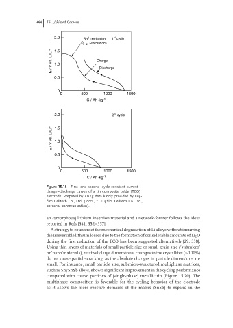
Figure 15.18 First- and second- cycle constant current
charge–discharge curves of a tin composite oxide (TCO)
electrode. Prepared by using data kindly provided by Fuji-
film Celltech Co., Ltd. (Idota, Y. Fujifilm Celltech Co. Ltd.,
personal communication).
an (amorphous) lithium insertion material and a network-former follows the ideas
reported in Refs [341, 352–357].
A strategy to counteract the mechanical degradation of Li alloys without incurring
the irreversible lithium losses due to the formation of considerable amounts of Li 2 O
during the first reduction of the TCO has been suggested alternatively [29, 358].
Using thin layers of materials of small particle size or small grain size (‘submicro’
or ‘nano’materials), relatively large dimensional changes in the crystallites (∼100%)
do not cause particle cracking, as the absolute changes in particle dimensions are
small. For instance, small particle size, submicro-structured multiphase matrices,
such as Sn/SnSb alloys, show a significant improvement in the cycling performance
compared with coarse particles of (single-phase) metallic tin (Figure 15.20). The
multiphase composition is favorable for the cycling behavior of the electrode
as it allows the more reactive domains of the matrix (SnSb) to expand in the