
Page 538 - Handbook of Battery Materials
P. 538
16.4 Models for SEI Electrodes 511
of phases mentioned above. W represents the Warburg impedance on the solution
side of the SEI electrode.
In many cases, the Nyquist plot for SEI electrodes consists of only one, almost
perfect, semicircle whose diameter increases with storage time (and a Warburg
section at low frequencies). For these cases the following can be concluded: the SEI
consists of only one SL, R CT1 , R GB , and R CT2 R SEI ; C GB , C E/sol , and C E/SE C SEI .
Under these conditions the SEI can be represented by a single RC element-R SEI and
C SEI (and the Warburg element). In other cases, aside from the Warburg section,
the Nyquist plot can consist of two semicircles [123–125], many semicircles [18, 23,
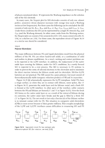
124], or a shallow arc [126]. For these cases, the equivalent circuit of Figure 16.14
or a similar one should be considered.
16.4.2
Polymer Electrolytes
The major differences between PEs and liquid electrolytes result from the physical
stiffness of the PE. PEs are either hard-to-soft solids, or a combination of solid
and molten in phases equilibrium. As a result, wetting and contact problems are
to be expected at the Li/PE interface. In addition, the replacement of the native
oxide layer covering the lithium, under the OCV conditions, by a newly formed
SEI is expected to be a slow process. The SEI is necessary in PE systems in
order to prevent the entry of solvated electrons to the electrolyte and to minimize
the direct reaction between the lithium anode and the electrolyte. SEI-free Li/PE
batteries are not practical. The SEI cannot be a pure polymer, but must consist of
thermodynamically stable inorganic reduction products of PE and its impurities.
Figure 16.15 [6] schematically represents the Li/PE interphase. Solid PEs have
a rough surface, so when they are in contact with lithium, some spikes, like ‘2’
in Figure 16.15, penetrate the oxide layer and the lithium metal, and a fresh SEI
is formed at the Li/PE interface. In other parts of the interface, softer contacts
between the PE and lithium are formed (‘1’ and ‘3’ in Figure 16.15). Here the fresh
SEI forms on the native oxide layer or, as a result of the retreat of lithium during
its corrosion, the native oxide layer breaks and the gap is filled by a fresh SEI
(‘1’ in Figure 16.15). The net result is that only a fraction (θ)ofthe lithiumsurface
is in intimate contact with the PE. The situation in composite solid electrolytes
(CPEs) is more severe because of their greater stiffness. This complex morphology
of the Li/PE and Li/CPE interfaces causes difficulties in measuring SEI and PE
C E/ SE C SEI C GB C 1/2 C SEI C GB C SE/ sol
W
R R SEI R GB R 1/2 R SEI R GB R
CT 1 CT 2
SL1 SL2
Figure 16.14 Equivalent circuit for two sublayer poly-
heteromicrophase SEI (for notation, see text) [122].