
Page 228 - Handbook of Biomechatronics
P. 228
Upper-Limb Prosthetic Devices 225
(A) (C)
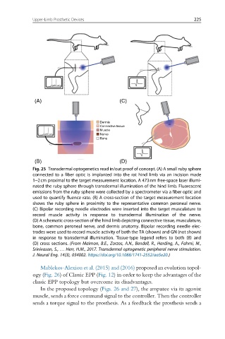
Dermis
Connective tissue
Muscle
Nerve
Bone
(B) (D)
Fig. 25 Transdermal optogenetics read in/out proof of concept. (A) A small ruby sphere
connected to a fiber optic is implanted into the rat hind limb via an incision made
1–2cm proximal to the target measurement location. A 473nm free-space laser illumi-
nated the ruby sphere through transdermal illumination of the hind limb. Fluorescent
emissions from the ruby sphere were collected by a spectrometer via a fiber optic and
used to quantify fluence rate. (B) A cross-section of the target measurement location
shows the ruby sphere in proximity to the representative common peroneal nerve.
(C) Bipolar recording needle electrodes were inserted into the target musculature to
record muscle activity in response to transdermal illumination of the nerve.
(D) A schematic cross-section of the hind limb depicting connective tissue, musculature,
bone, common peroneal nerve, and dermis anatomy. Bipolar recording needle elec-
trodes were used to record muscle activity of both the TA (shown) and GN (not shown)
in response to transdermal illumination. Tissue-type legend refers to both (B) and
(D) cross sections. (From Maimon, B.E., Zorzos, A.N., Bendell, R., Harding, A., Fahmi, M.,
Srinivasan, S., … Herr, H.M., 2017. Transdermal optogenetic peripheral nerve stimulation.
J. Neural Eng. 14(3), 034002. https://doi.org/10.1088/1741-2552/aa5e20.)
Mablekos-Alexiou et al. (2015) and (2016) proposed an evolution topol-
ogy (Fig. 26) of Classic EPP (Fig. 12) in order to keep the advantages of the
classic EPP topology but overcome its disadvantages.
In the proposed topology (Figs. 26 and 27), the amputee via its agonist
muscle, sends a force command signal to the controller. Then the controller
sends a torque signal to the prosthesis. As a feedback the prosthesis sends a