
Page 229 - Handbook of Biomechatronics
P. 229
226 Georgios A. Bertos and Evangelos G. Papadopoulos
Agonist and antagonist
muscles Inductive powering
system
Master robots
for agonist and antagonist
muscles
F ag
F ant Slave
q s motor
x ag
x ant
q s ,t e
Residual arm
Force
sensors
t s
Prosthesis
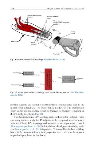
Fig. 26 Biomechatronic EPP topology (Mablekos-Alexiou, 2016).
Force
Agonist muscle Master robot
Communication channels and control (1 D.o.F. prosthesis) Environment
(linear actuator)
Position Torque
Slave robot
Force Position
Antagonist muscle Master robot
(linear actuator)
Position
Fig. 27 Master/slave control topology used in the Biomechatronic EPP (Mablekos-
Alexiou, 2016).
position signal to the controller and then this is communicated back to the
master robot as feedback. The master robots (leadscrews with motors) and
other electronics use battery which is charged via inductive coupling as
shown in the prosthesis (Fig. 26).
The Biomechatronic EPP topology has been shown (for 1 subject—with
a pending research study for 15 subjects) to have equivalent performance
with the Classic EPP topology and superior to the myoelectric control
(Kontogiannopoulos et al., 2018). Initial thermal and power feasibility anal-
ysis (Moutopoulou et al., 2015) is positive. This could be the best building
block with inherent subconscious properties that could enable superior
upper-limb prostheses in the future.