
Page 78 - Handbook of Biomechatronics
P. 78
Sensors and Transducers 73
Fig. 13 Circuit diagram with a thermistor. As the temperature sensed varies, the bright-
ness of the lightbulb changes.
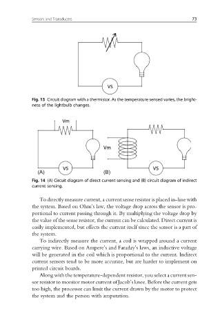
Fig. 14 (A) Circuit diagram of direct current sensing and (B) circuit diagram of indirect
current sensing.
To directly measure current, a current sense resistor is placed in-line with
the system. Based on Ohm’s law, the voltage drop across the sensor is pro-
portional to current passing through it. By multiplying the voltage drop by
the value of the sense resistor, the current can be calculated. Direct current is
easily implemented, but effects the current itself since the sensor is a part of
the system.
To indirectly measure the current, a coil is wrapped around a current
carrying wire. Based on Ampere’s and Faraday’s laws, an inductive voltage
will be generated in the coil which is proportional to the current. Indirect
current sensors tend to be more accurate, but are harder to implement on
printed circuit boards.
Along with the temperature-dependent resistor, you select a current sen-
sor resistor to monitor motor current of Jacob’s knee. Before the current gets
too high, the processor can limit the current drawn by the motor to protect
the system and the person with amputation.