
Page 83 - Handbook of Biomechatronics
P. 83
78 Jeff Christenson
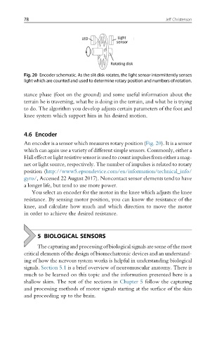
Fig. 20 Encoder schematic. As the slit disk rotates, the light sensor intermittently senses
light which are counted and used to determine rotary position and numbers of rotation.
stance phase (foot on the ground) and some useful information about the
terrain he is traversing, what he is doing in the terrain, and what he is trying
to do. The algorithm you develop adjusts certain parameters of the foot and
knee system which support him in his desired motion.
4.6 Encoder
An encoder is a sensor which measures rotary position (Fig. 20). It is a sensor
which can again use a variety of different simple sensors. Commonly, either a
Hall effect or light resistivesensor is usedto count impulsesfrom either a mag-
net or light source, respectively. The number of impulses is related to rotary
position (http://www5.epsondevice.com/en/information/technical_info/
gyro/, Accessed 22 August 2017). Noncontact sensor elements tend to have
a longer life, but tend to use more power.
You select an encoder for the motor in the knee which adjusts the knee
resistance. By sensing motor position, you can know the resistance of the
knee, and calculate how much and which direction to move the motor
in order to achieve the desired resistance.
5 BIOLOGICAL SENSORS
The capturing and processing of biological signals are some of the most
critical elements of the design of biomechatronic devices and an understand-
ing of how the nervous system works is helpful in understanding biological
signals. Section 5.1 is a brief overview of neuromuscular anatomy. There is
much to be learned on this topic and the information presented here is a
shallow skim. The rest of the sections in Chapter 5 follow the capturing
and processing methods of motor signals starting at the surface of the skin
and proceeding up to the brain.