
Page 79 - Handbook of Biomechatronics
P. 79
74 Jeff Christenson
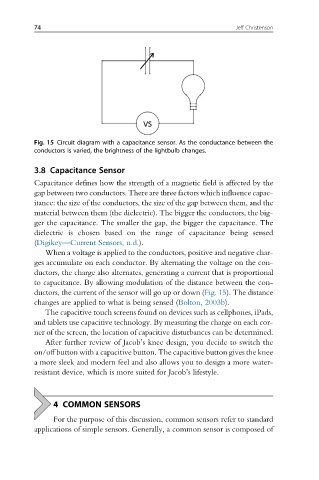
Fig. 15 Circuit diagram with a capacitance sensor. As the conductance between the
conductors is varied, the brightness of the lightbulb changes.
3.8 Capacitance Sensor
Capacitance defines how the strength of a magnetic field is affected by the
gap between two conductors. There are three factors which influence capac-
itance: the size of the conductors, the size of the gap between them, and the
material between them (the dielectric). The bigger the conductors, the big-
ger the capacitance. The smaller the gap, the bigger the capacitance. The
dielectric is chosen based on the range of capacitance being sensed
(Digikey—Current Sensors, n.d.).
When a voltage is applied to the conductors, positive and negative char-
ges accumulate on each conductor. By alternating the voltage on the con-
ductors, the charge also alternates, generating a current that is proportional
to capacitance. By allowing modulation of the distance between the con-
ductors, the current of the sensor will go up or down (Fig. 15). The distance
changes are applied to what is being sensed (Bolton, 2003b).
The capacitive touch screens found on devices such as cellphones, iPads,
and tablets use capacitive technology. By measuring the charge on each cor-
ner of the screen, the location of capacitive disturbances can be determined.
After further review of Jacob’s knee design, you decide to switch the
on/off button with a capacitive button. The capacitive button gives the knee
a more sleek and modern feel and also allows you to design a more water-
resistant device, which is more suited for Jacob’s lifestyle.
4 COMMON SENSORS
For the purpose of this discussion, common sensors refer to standard
applications of simple sensors. Generally, a common sensor is composed of