
Page 142 - Handbook of Civil Engineering Calculations, Second Edition
P. 142
STRUCTURAL STEEL DESIGN 1.125
Angular
Section displacement Moment W 1
A –
B + M p M p
C
D – M p M p
E +
_____
Total 2M p
Then 2M p 532.8 ; M p 266.4 ft·kips (361.24 kN·m).
4. Assume the composite mode of failure and compute M p
Since this results from superposition of the two preceding modes, the angular displace-
ments and the external work may be obtained by adding the algebraic values previously
found. Thus, W E 740 + 532.8 1272.8 . Then the tabulation is as shown:
Angular
Section displacement Moment W 1
A –
B
C +2 M p 2M p
D –2 M p 2M p
E +
_____
Total 4M p
Then 4M p 1272.8 ; M p 318.2 ft·kips (431.48 kN·m).
5. Select the highest value of M p as the correct result
Thus, M p 318.2 ft·kips (431.48 kN·m). The structure fails through the formation of
plastic hinges at C and D. That a hinge should
appear at D rather than at B is plausible when
it is considered that the bending moments in-
duced by the two loads are of like sign at D
but of opposite sign at B.
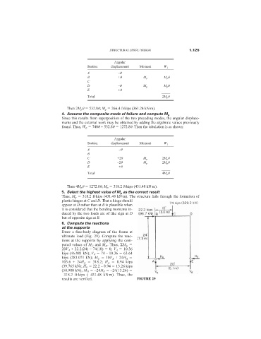
6. Compute the reactions
at the supports
Draw a free-body diagram of the frame at
ultimate load (Fig. 29). Compute the reac-
tions at the supports by applying the com-
puted values of M C and M D . Thus, M E
20V A + 22.2(24) – 74(10) 0; V A 10.36
kips (46.081 kN); V E 74 – 10.36 63.64
kips (283.071 kN); M C 10V A + 24H A
103.6 + 24H A 318.2; H A 8.94 kips
(39.765 kN); H E 22.2 – 8.94 13.26 kips
(58.980 kN); M D –24H E –24(13.26)
–318.2 ft·kips (–431.48 kN·m). Thus, the
results are verified. FIGURE 29