
Page 137 - Handbook of Civil Engineering Calculations, Second Edition
P. 137
1.120 STRUCTURAL STEEL ENGINEERING AND DESIGN
ANALYSIS OF A TWO-SPAN BEAM
WITH CONCENTRATED LOADS
The continuous W18 45 beam in Fig. 24 carries two equal concentrated loads having
the locations indicated. Disregarding the weight of the beam, compute the ultimate value
of these loads, using both the static and the mechanism method.
Calculation Procedure:
1. Construct the force and
bending-moment diagrams
The continuous beam becomes un-
FIGURE 24 stable when a plastic hinge forms
at C and at another section. The
bending-moment diagram has vertices at B and D, but it is not readily apparent at which
of these sections the second hinge will form. The answer is found by assuming a plastic
hinge at B and at D, in turn, computing the corresponding value of P u , and selecting the lesser
value as the correct result. Part a will use the static method; part b, the mechanism method.
Assume, for part a, a plastic hinge at B and C. In Fig. 25, construct the force diagram and
bending-moment diagram for span AC. The moment diagram may be drawn in the manner
shown in Fig. 25b or c, whichever is preferred. In Fig. 25c, ACH represents the moments
that would exist in the absence of restraint at C, and ACJ represents, in absolute value, the
moments induced by this restraint. Compute the load P u associated with the assumed hinge
location. From previous calculation procedures, M p 268.8 ft·kips (364.49 kN·m); then
M B 14 16P u /30 – 14M p /30 M p ; P u 44(268.8)/224 52.8 kips (234.85 kN).
2. Assume another hinge location and compute the ultimate load
associated with this location
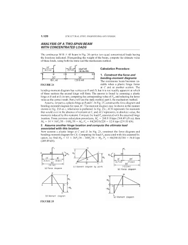
Now assume a plastic hinge at C and D. In Fig. 25, construct the force diagram and
bending-moment diagram for CE. Computing the load P u associated with this assumed lo-
cation, we find M D 12 24P u /36 – 24M p /36 M p ; P u 60(268.8)/288 56.0 kips
(249.09 kN).
FIGURE 25