
Page 134 - Handbook of Civil Engineering Calculations, Second Edition
P. 134
STRUCTURAL STEEL DESIGN 1.117
Using data from the AISC Manual,
3
3
we have Z 89.6 in (1468.54 cm ).
Then M p f y Z 36(89.6)/12 268.8
ft·kips (364.49 kN·m).
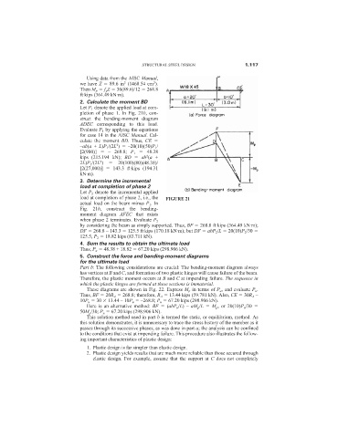
2. Calculate the moment BD
Let P 1 denote the applied load at com-
pletion of phase 1. In Fig. 21b, con-
struct the bending-moment diagram
ADEC corresponding to this load.
Evaluate P 1 by applying the equations
for case 14 in the AISC Manual. Cal-
culate the moment BD. Thus, CE
2
–ab(a + L)P 1 /(2L ) –20(10)(50)P 1 /
[2(900)] – 268.8; P 1 48.38
2
kips (215.194 kN); BD ab (a +
3
2L)P 1 /(2L ) 20(100)(80)(48.38)/
[2(27,000)] 143.3 ft·kips (194.31
kN·m).
3. Determine the incremental
load at completion of phase 2
Let P 2 denote the incremental applied
load at completion of phase 2, i.e., the FIGURE 21
actual load on the beam minus P 1 . In
Fig. 21b, construct the bending-
moment diagram AFEC that exists
when phase 2 terminates. Evaluate P 2
by considering the beam as simply supported. Thus, BF 268.8 ft·kips (364.49 kN·m);
DF 268.8 – 143.3 125.5 ft·kips (170.18 kN·m); but DF abP 2 /L 20(10)P 2 /30
125.5; P 2 18.82 kips (83.711 kN).
4. Sum the results to obtain the ultimate load
Thus, P u 48.38 + 18.82 67.20 kips (298.906 kN).
5. Construct the force and bending-moment diagrams
for the ultimate load
Part b: The following considerations are crucial: The bending-moment diagram always
has vertices at B and C, and formation of two plastic hinges will cause failure of the beam.
Therefore, the plastic moment occurs at B and C at impending failure. The sequence in
which the plastic hinges are formed at these sections is immaterial.
These diagrams are shown in Fig. 22. Express M p in terms of P u , and evaluate P u .
Thus, BF 20R A 268.8; therefore, R A 13.44 kips (59.781 kN). Also, CE 30R A –
10P u 30 13.44 – 10P u –268.8; P u 67.20 kips (298.906 kN).
Here is an alternative method: BF (abP u /L) – aM p /L M p , or 20(10)P u /30
50M p /30; P u 67.20 kips (298.906 kN).
This solution method used in part b is termed the static, or equilibrium, method. As
this solution demonstrates, it is unnecessary to trace the stress history of the member as it
passes through its successive phases, as was done in part a; the analysis can be confined
to the conditions that exist at impending failure. This procedure also illustrates the follow-
ing important characteristics of plastic design:
1. Plastic design is far simpler than elastic design.
2. Plastic design yields results that are much more reliable than those secured through
elastic design. For example, assume that the support at C does not completely