
Page 133 - Handbook of Civil Engineering Calculations, Second Edition
P. 133
1.116 STRUCTURAL STEEL ENGINEERING AND DESIGN
Thus, for a rectangle, C bdf y /2, a
2
d/2, and M p aC bd f y /4. For a circle, C
d f y /8, a 4d(3 ), and M p aC
2
3
d f y /6. For a W16 40, C /2(11.77 sq.in.)
1
5.885f y .
To locate the action lines, refer to the
Manual and note the position of the cen-
troidal axis of the WT8 20 section, i.e., a
section half the size of that being considered.
Thus, a 2(8.00 – 1.82) 12.36 in.
(313.944 mm); M p aC 12.36(5.885f y )
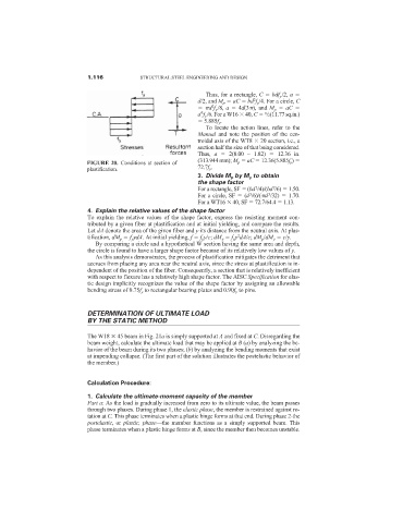
FIGURE 20. Conditions at section of
plastification. 72.7f y .
3. Divide M p by M y to obtain
the shape factor
2
2
For a rectangle, SF (bd /4)/(bd /6) 1.50.
3
3
For a circle, SF (d /6)/( d /32) 1.70.
For a WT16 40, SF 72.7/64.4 1.13.
4. Explain the relative values of the shape factor
To explain the relative values of the shape factor, express the resisting moment con-
tributed by a given fiber at plastification and at initial yielding, and compare the results.
Let dA denote the area of the given fiber and y its distance from the neutral axis. At plas-
2
tification, dM p f y ydA. At initial yielding, f f y y/c; dM y f y y dA/c; dM p /dM y c/y.
By comparing a circle and a hypothetical W section having the same area and depth,
the circle is found to have a larger shape factor because of its relatively low values of y.
As this analysis demonstrates, the process of plastification mitigates the detriment that
accrues from placing any area near the neutral axis, since the stress at plastification is in-
dependent of the position of the fiber. Consequently, a section that is relatively inefficient
with respect to flexure has a relatively high shape factor. The AISC Specification for elas-
tic design implicitly recognizes the value of the shape factor by assigning an allowable
bending stress of 0.75f y to rectangular bearing plates and 0.90f y to pins.
DETERMINATION OF ULTIMATE LOAD
BY THE STATIC METHOD
The W18 45 beam in Fig. 21a is simply supported at A and fixed at C. Disregarding the
beam weight, calculate the ultimate load that may be applied at B (a) by analyzing the be-
havior of the beam during its two phases; (b) by analyzing the bending moments that exist
at impending collapse. (The first part of the solution illustrates the postelastic behavior of
the member.)
Calculation Procedure:
1. Calculate the ultimate-moment capacity of the member
Part a: As the load is gradually increased from zero to its ultimate value, the beam passes
through two phases. During phase 1, the elastic phase, the member is restrained against ro-
tation at C. This phase terminates when a plastic hinge forms at that end. During phase 2-the
postelastic, or plastic, phase—the member functions as a simply supported beam. This
phase terminates when a plastic hinge forms at B, since the member then becomes unstable.