
Page 132 - Handbook of Civil Engineering Calculations, Second Edition
P. 132
STRUCTURAL STEEL DESIGN 1.115
Expressing the relationships among
the tensile stresses, we have L
s A L A /E s B L B /E s C L C /E; therefore,
s A s C , and s A s B L B /L A 0.75s B
for this arrangement of rods. Since s B
is the maximum stress, the allowable
stress first appears in rod B.
2. Evaluate the stresses at the
instant the load attains its
allowable value
Calculate the load carried by each rod,
and sum these loads to find P allow .
Thus s B 22,000 lb/sq.in. (151,690.0
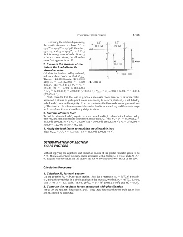
kPa); s B 0.75(22,000) 16,500 FIGURE 19
lb/sq.in. (113,767.5 kPa); P A P C
16,500(1.2) 19,800 lb (88,070.4
N); P B 22,000(1.0) 22,000 lb (97,856.0 N); P allow 2(19,800) + 22,000 61,600 lb
(273,996.8 N).
Next, consider that the load is gradually increased from zero to its ultimate value.
When rod B attains its yield-point stress, its tendency to deform plastically is inhibited by
rods A and C because the rigidity of the bar constrains the three rods to elongate uniform-
ly. The structure therefore remains stable as the load is increased beyond the elastic range
until rods A and C also attain their yield-point stress.
3. Find the ultimate load
To find the ultimate load P u , equate the stress in each rod to f y , calculate the load carried by
each rod, and sum these loads to find the ultimate load P u . Thus, P A P C 36,000(1.2)
43,200 lb (192,153.6 N); P B 36,000(1.0) 36,000 lb (160,128.0 N); P u 2(43,200) +
36,000 122,400 lb (544,435.2 N).
4. Apply the load factor to establish the allowable load
Thus, P allow P u /LF 122,400/1.85 66,200 lb (294,457.6 N).
DETERMINATION OF SECTION
SHAPE FACTORS
Without applying the equations and numerical values of the plastic modulus given in the
AISC Manual, determine the shape factor associated with a rectangle, a circle, and a W16
40. Explain why the circle has the highest and the W section the lowest factor of the three.
Calculation Procedure:
1. Calculate M y for each section
2
Use the equation M y Sf y for each section. Thus, for a rectangle, M y bd f y /6. For a cir-
3
cle, using the properties of a circle as given in the Manual, we find M y d f y /32. For a
2
3
3
W16 40, A 11.77 sq.in. (75.940 cm ), S 64.4 in (1055.52 cm ), and M y 64.4f y .
2. Compute the resultant forces associated with plastification
In Fig. 20, the resultant forces are C and T. Once these forces are known, their action lines
and M p should be computed.