Page 128 - Handbook of Civil Engineering Calculations, Second Edition
P. 128

STRUCTURAL STEEL DESIGN               1.111

                              Calculation Procedure:

                              1. Record the basic values of the previous calculation procedure
                              The beam-column factors were devised in an effort to reduce the labor entailed in analyz-
                              ing a given member as a beam column when f a /F a > 0.15. They are defined by B   A/S
                                                            4
                                                                      4
                                                         6
                              per inch (decimeter); a   0.149   10 I in (6201.9I dm ).
                                Let P denote the applied axial load and P allow the axial load that would be permitted in
                              the absence of bending. The equations given in the previous procedure may be trans-
                                                            2
                              formed to P + BMC m (F a /F b )a/[a – P(KL) ]   P allow , and PF a /(0.6f y ) + BMF a /F b   P allow ,
                              where KL, B, and a are evaluated with respect to the plane of bending.
                                The basic values of the previous procedure are P   160 kips (711.7 kN); M   31.5
                              ft·kips (42.71 kN·m); F b   22 kips/sq.in. (151.7 MPa); C m   0.793.
                              2. Obtain the properties of the section
                                                                             2
                              From the Manual for a W12   53, A   15.59 sq.in. (100.587 cm ); B x   0.221 per inch
                                                     6
                                                        4
                                                                   3
                                                                      4
                              (8.70 per meter); a x   63.5   10 in (264.31   10 dm ). Then when KL   20 ft (6.1 m),
                              P allow   209 kips (929.6 kN).
                              3. Substitute in the first transformed equation
                              Thus, F a   P allow /A   209/15.59   13.41 kips/sq.in. (92.461 MPa), P(KL)   160(240)
                                                                                            2
                                                                                  2
                                                                            2
                                     6
                                                            2
                              9.22   10 kip·sq.in. (2.648   10 kN·m ), and a x /[a x – P(KL) ]   63.5/(63.5 – 9.22)
                                                       4
                              1.17; then 160 + 0.221(31.5)(12)(0.793)(13.41/22)(1.17)   207 < 209 kips (929.6 kN).
                              This is acceptable.
                              4. Substitute in the second transformed equation
                              Thus, 160(13.41/22) + 0.221(31.5)(12)(13.41/22)   148 < 209 kips (929.6 kN). This is
                              acceptable. The W12   53 section is therefore satisfactory.
                              NET SECTION OF A TENSION MEMBER
                                     1
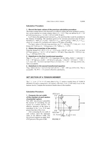
                              The 7   /4 in. (177.8   6.35 mm) plate in Fig. 17 carries a tensile force of 18,000 lb
                                                                       3
                              (80,064.0 N) and is connected to its support with three  /4-in. (19.05-mm) rivets in the
                              manner shown. Compute the maximum tensile stress in the member.
                              Calculation Procedure:
                              1. Compute the net width
                              of the member at each section
                              of potential rupture
                              The AISC  Specification prescribes
                              the manner of calculating the net
                              section of a tension member. The
                              effective diameter of the holes is
                              considered to be  /8 in. (3.18 mm)
                                           1
                              greater than that of the rivets.
                                After computing the net width of
                              each section, select the minimum
                              value as the effective width. The
                              Specification imposes an upper limit
                              of 85 percent of the gross width.  FIGURE 17
   123   124   125   126   127   128   129   130   131   132   133